Hi everyone,
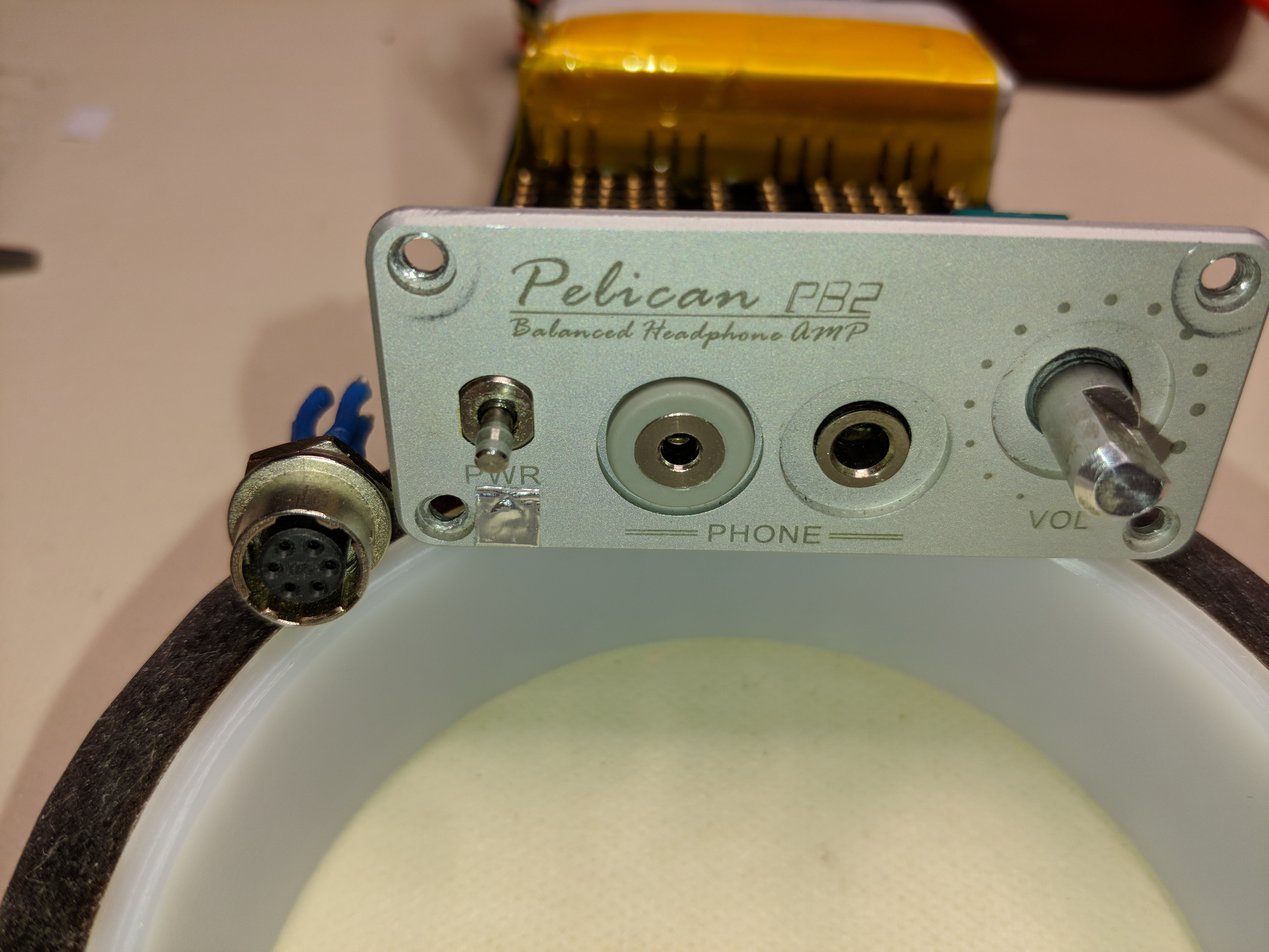
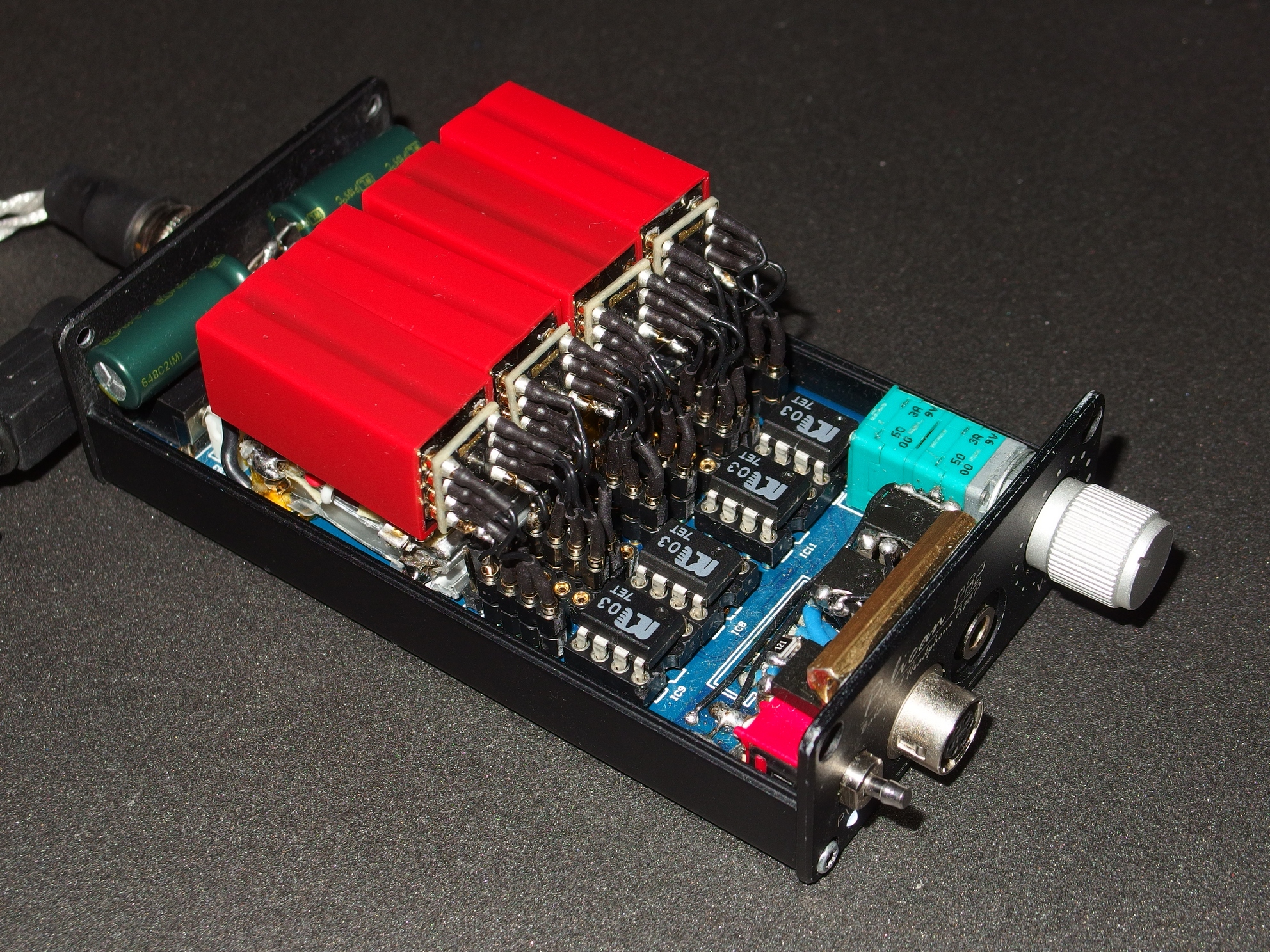
a few weeks ago I swap my Centrance mini M8 to a set of ibasso pb2 + db2. I liked the possibility of replacing the op-amp, the 32V output swing and the DIY design. No battery was inside, so I tested PB2 with an external 16V power supply.
First of all, I measured the supply voltage to the op-amp - it was +/- 8V, which fully corresponds to the input voltage of 16V. Accordingly the maximum output amplitude voltage swing can not be greater than 16V (+/- 8V), and this is correctly only for rail-to-rail op-amp. But how do they state the output amplitude swing of the 32V if even on one wire of the balanced output the maximum amplitude peak can be + 8V, and on the other output, in the opposite phase, minimum -8V. Therfore the amplitude of 16V on the balance output is obtained.
I began to understand the power circuit in order to increase the voltage. Making modification of the FiiO X7 amplifier I realized that the higher power supply of the op-amp, the better sound at the output.
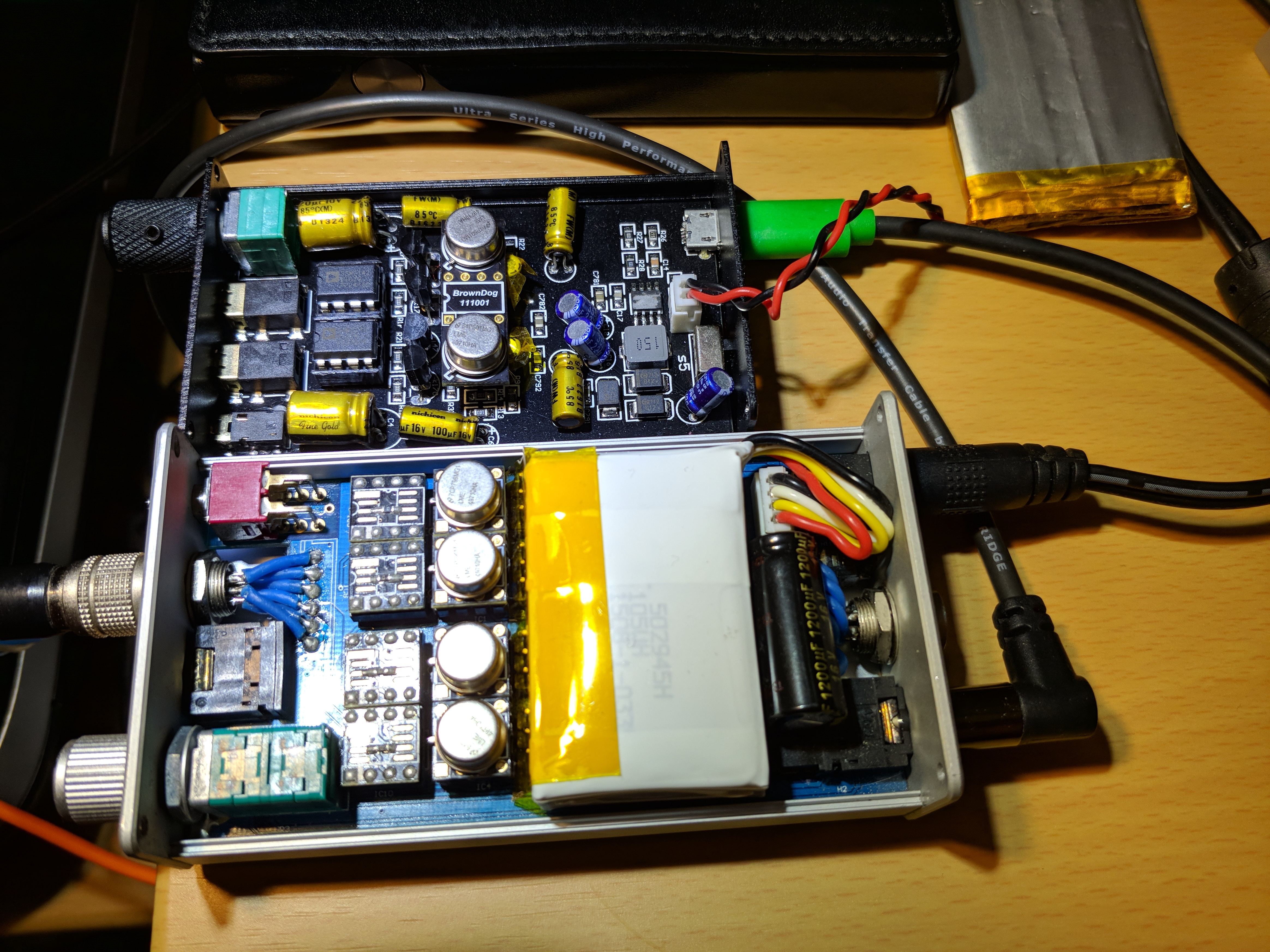
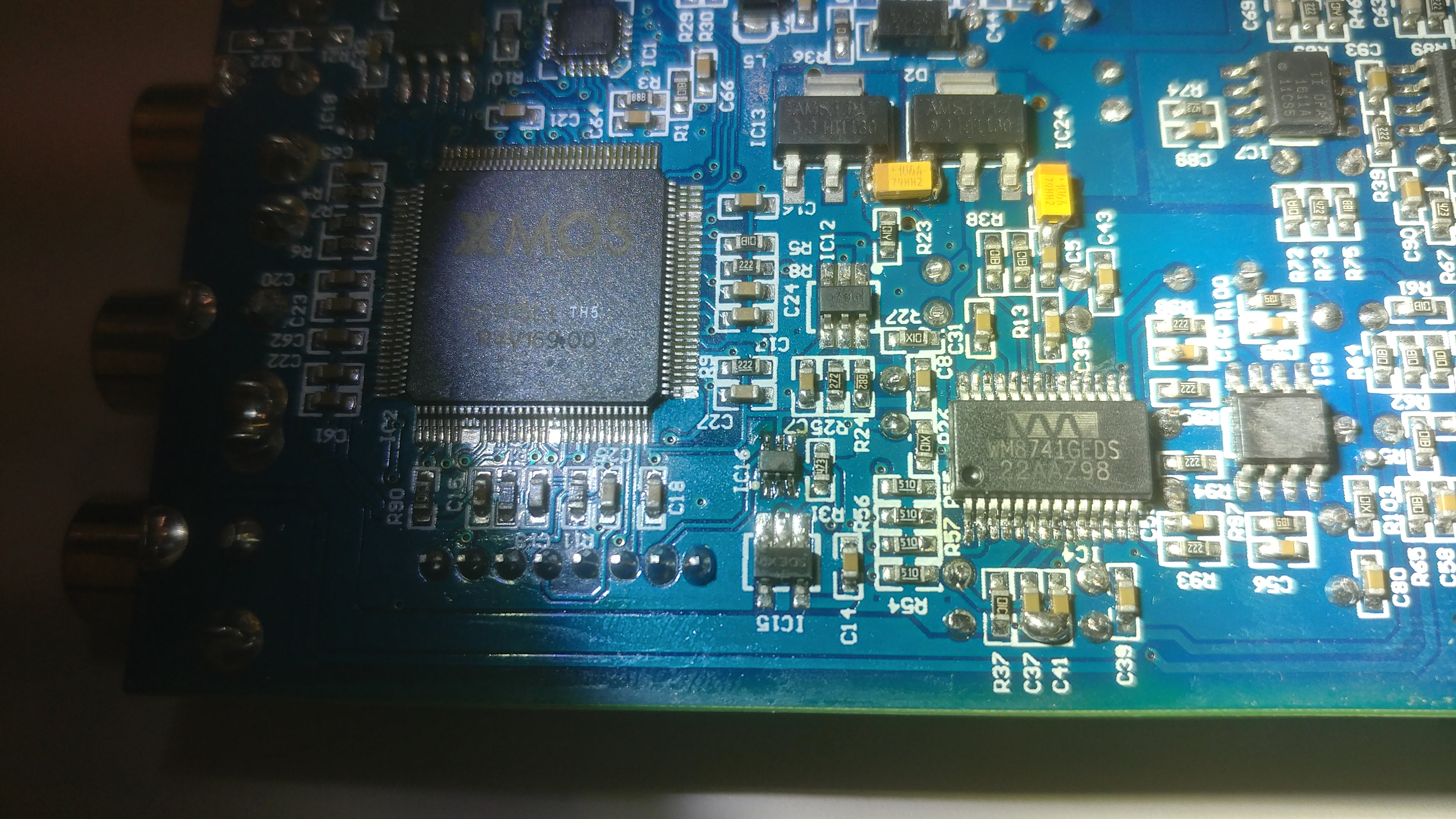
For a long time I could not find the microcchips names with erased labels, but when I make a reverse engineering of the PB2 PCB, the idea of power supply inmplementation became clear. The PB2 power supply is taken from an external source or internal battery, and the middle point is created by the microchip divider. Thus we obtain from a unipolar input voltage a bipolar supply of the op-amp. Since the characteristics of this chip allow to feed it with voltage up to 40V, I tried to connect an external power source 24V from the photo printer. !But before connecting it is necessary to change the input capacitor to a higher voltage, I replaced it to 2200u35V! The sound quality increased significantly. The resolution and depth became amazing.
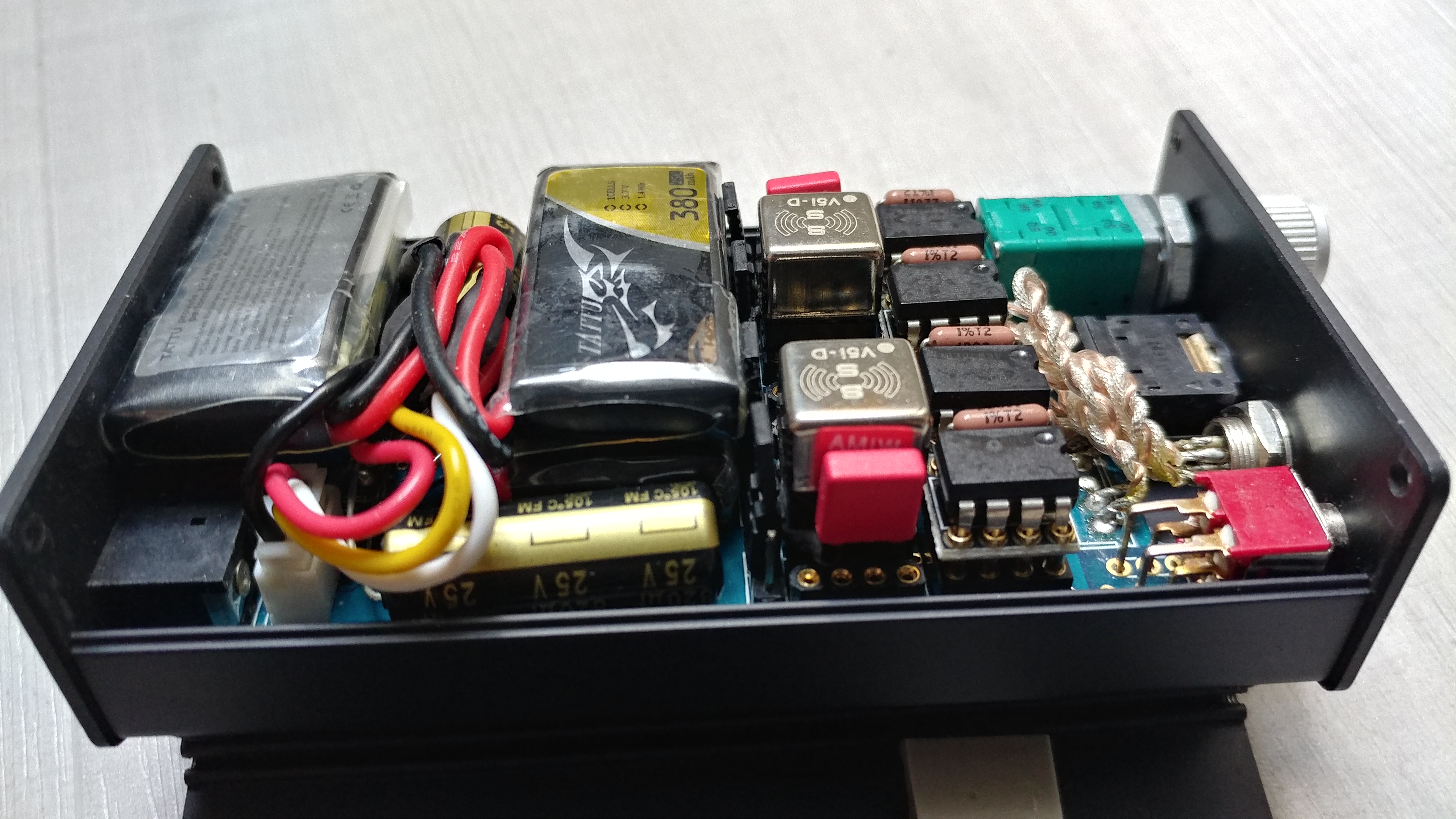
After that, I decided to raise the voltage as much as possible. For this, I bought two LiPo 4S 14.8V 1000mA 70C batteries and connected them in series. It turned out about 30V at the input of the amplifier and the power supply of the op-amp became +/- 15V. Just in case, I changed all the tantalum capacitors in the power supply rails, since the marking is flawed and it's not clear what maximum voltage they can withstand, replaced it to 220u16V.
And on this input voltage has burned a 2.2 Ohm resistor that limits the starting current when the power is turned on. Therefore, it must be replaced by a more powerful or greater resistance. It can not be short-circuited, since when the power is turned on, a strong current surge occurs when the capacitor is charged and the power switch contacts are burned.
Now the amplitude output swing of the amplifier can reach 30V. And the sound of the amplifier became unbeatable. All the same, the power supply of an op-amp for good sound should be not less than +/- 12V.
Now I am working on DB2 modification and it became sounds much better.
PS Sorry for my "Google translated" English
")