


Paladin79
Previously MOT: Cables For Less


Last edited:
Yeah, It is a pretty good adapter. I don't know why I'm getting a difference in sound. Is there any way to change it? Or is this just something that comes with the DIY territory and using different materials?
Yeah, for sure. I used some heatshrink to hold the braided sleeve to the wire, and then one more layer over it it secure the sleeve to the jacks which I over heated a bit so it would sort of melt into the grooves of the braided sleeve. Now the sleeve is very secure. If you look closely at that heat shrink you can see the light marks of the braid. This sacrificed a bit of flexibility, but it's ok since this wire is not very flexible all-together with all the layers.
If i want to make a cable with 8 wire braid, how is it wired?
3L, 3R, 2Ground?
***edit
Oh wait sorry.
so 8 wires, divide into 2 for L R channel = 4 wires each
at the TRS jack, combine -ve from L R = 2L + 2R
That means there will be 2 wires on Tip, 2 wires on Ring, 4 wires on Sleeve right?
Thank you very much Allanmarcus.Correct
You can change the connectors on the adapter but I doubt that would change the sound. If there is anyone out there who can actually hear a difference between connectors I have yet to meet them. I have heard cables that can track sound more accurately than others, or cables that offer a different sound when hand braided (could be from a lack of shielding or poor construction) but at such a short distance I am not sure what to say. Impedance is less of a factor at short distances,( under a meter I believe) and that is made up of inductive reactance, capacitive reactance and resistance. Please do not take this the wrong way but sometimes you can go into a test expecting a difference. I recently read where the same wine was put in two different bottles, one was marked $20, the other $5.00 and sommeliers consistently picked the $20 bottle as the better. The labels were reversed without them seeing it and then the opposite wines were chosen when marked $20. You did a sort of blind test by having someone else listen so you were as objective as possible and if the tests were done the same way, there probably is a difference. Audio can be a funny thing sometimes. I also once read where there were some blind tests done with speaker wires where the equipment was totally covered. 7 of 10 people chose some $1.00 cables over some that were $100 up and they were supposed audiophiles. On the adapter you built, make absolutely certain the channels were not reversed and that you are getting good channel separation, if all things are equal, and your diy cable is built properly, it must be a slight difference in the wire itself IMHO>
Here are a few things I would try.
1) set your multi-meter to Ohm/automatic. Probe left/right, left/common, right/common. All of these should report 0 ohm as there should be no resistance between two things that should not be connected. If you get another other reading, you have something going on. Might be a short, Might be a fluty cable. Might be a faulty connector. Might be a faulty solder joint.
2) If all the Ohm readings are fine, I would simply reflow the joints.

I see, thank you very much. It bugs my eyes visually but electrically it should look good from the equipment.Penmarker:
2 x right x hot
2 x right x common
2 x left x hot
2 x left x common
Perfect symmetry, exec though 4 wires in this case are connected to ground.
If I get a chance I will try to post a small list of basics on soldering along with photos so those new to soldering will have a good idea what to look for.

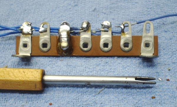
Let us examine the lugs numbered left to right.
- This one is just about perfect. All wires and the surface of the lug are covered with solder. Although it doesn't show in the photo there is no ball of solder on the back. This is sometimes a mistake of those with limited experience.
- There are only two wires in this lug and both of them are soldered on both front and back. Even so, the joint likely would be rejected by quality control. However there is no law that says you have to fill the hole. The advantage of this soldering job is that it would be easy to add wires to this lug later. Since writing this I have been informed that production lines which are assembling tube equipment in the old way don't want the hole filled. This allows the quality control inspector to easily tell a good soldering job from a bad one. That makes sense to me. So don't fill the hole and you'll likely pass QC.
- In this one the solderer has applied enough heat but used far too much solder. Always watch where your solder is going. It is likely you think you don't have quite enough solder on a lug but it is just running away as fast as you apply it. The mane mistake made here was to hold the iron on the lug much too long applying too much heat and too much solder. When the lug is covered, take away the heat and solder. Know when to stop. If this terminal strip had been mounted in a real chassis the solder would have run down and shorted the lug to ground causing lots of headaches. I know because that has happened to me.
- This is the common mistake of rank beginners. The soldering iron was held above the lug, the solder melted and dropped onto the lug. The solder did adhere but the wires did not benefit from contact with the hot solder. The bottom wire is free to move around.
- This lug has two wires in it. The top wire was soldered very well but the bottom one was missed completely. A mistake of this kind usually happens when there are a large number of wires in the lug and the bottom one gets missed.
- The last one illustrates the breadboarding technique. The hook has been left more open then is recommended to show the principle more clearly.
Question about wiring, i got the sommer cable peacock for my hd800.
I plan to wire it for balanced, and use an adapter for unbalanced amp.
if i got this correct, i would wire the shield of each cable to the ground tab on the xlr, wire the red/white cable to + and -, and on the headphone side only wire the + and -, and not solder the shield?
then for the trs jack adapter (would use same cable), i would wire the shield on the xlr female side, but don't wire it on the trs jack? attach left and right minus to sleeve of the trs jack.
talking about this cable: https://www.rapidonline.com/sommer-cable-sc-peacock-mkii-speaker-cable-549508
i'm using neutrik jacks for everything else (XLR male, XLR female, TRS male)


