crinacle's IEM FR measurement database
Oct 24, 2017 at 3:51 AM Post #571 of 1,335
what is the correlation between BA IEMs impedance response.& output impedance of the source device? I mean can we predict which part of the sound will be impacted and how?
Taking Andro as an example, it gets brighter with the increase output impedance of the player, no doubt.
I did the test with my ATH-IM04 which is rated at 14ohms according to Audio Technica but the curve is not linear, in bass impedance is close to 100ohms then it decreases to 20ohms at 500Hz. Out of my player with 100ohms output impedance IM04 sound muddy with a lot of extra bass. Is that behaviour predictable?
Thanks
yeah sort of
It might be not be an universal truth because it will depend ultimately on amplifier design and is applicable only to standard BA (and multi BA) systems but
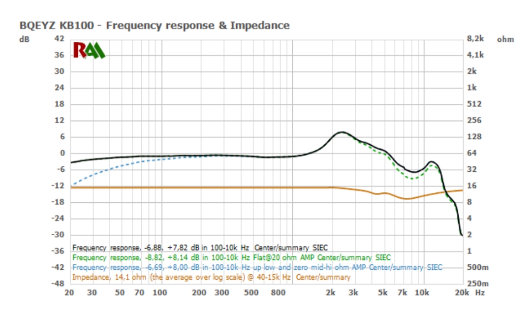
if impedance curve is down sloping (higher impedance at bass fr and lower on highs) then the bass will increase with higher impedance sound source or resistor in series. = muddy sound
if the impedance curve is rising (especially very low impedance at bass fr and very high on upper fr) then the bass will decrease with higher sound source or resistor in series = bass-less sound.
 
Oct 24, 2017 at 4:48 AM Post #573 of 1,335
what is the correlation between BA IEMs impedance response.& output impedance of the source device? I mean can we predict which part of the sound will be impacted and how?
Taking Andro as an example, it gets brighter with the increase output impedance of the player, no doubt.
I did the test with my ATH-IM04 which is rated at 14ohms according to Audio Technica but the curve is not linear, in bass impedance is close to 100ohms then it decreases to 20ohms at 500Hz. Out of my player with 100ohms output impedance IM04 sound muddy with a lot of extra bass. Is that behaviour predictable?
Thanks
while not precise for more than a general view(because oversimplified), you can get a fair idea of the expected changes in FR by looking at the gear as 2(or 3 with cable) resistors in series. think R1 is the amp's impedance, R2 the cable, R3 the IEM. the voltage at R3 is directly proportional to how loud the sound will get, and that voltage will change when R1 changes (basic ohm's law).
what makes it super annoying is that you have to calculate that for each frequency :weary:. assuming that R3 is supposed to be many times bigger than R1 and R2 (when we respect the impedance ratio), changing R1 a little isn't going to have much impact on the circuit. but if R3(the IEM) has a super low impedance somewhere, then any little change in R1 or R2 can affect V3(voltage at the IEM which is also loudness). as @SilverEars said it's all about the relative differences and variations.
if you increase R1 by using an amplifier with a bigger output impedance, V3 will go down a lot if R3 is small, but go down only a little if R3 is big. as the R3 value changes with frequencies(see impedance graph), changing R1 ends up changing the signature.

instead of making it look more complicated than it is, here is an example like some showed already by others(clic for full size).
imposef.jpg
the kind of magenta stuff labelled O2 is an IEM's frequency response measured with an O2 amp as source(around 0.6ohm, fairly stable over frequencies).
the cyan graph is the same IEM but I added a 5ohm resistor between the amp and the IEM. you can think of it as a 5.6ohm amp, or as a 0.6ohm amp + a 5ohm cable, for the IEM it's all the same, it all amounts to stuff happening "outside" :)
the yellow line is the impedance of the IEM over frequencies(ohm scale on the right of the graph). you can already guess the relation from looking at both FR, but just in case here is the difference between them:
imposef2.jpg
now it's hard not to see how the IEm's impedance(below) affects the signature change(above).
and while the magnitude of the variations will always depend on all the relative values, the direction of the change is very reliable. when you increase the amp's impedance, the IEM signature will go down the most at the frequencies where it has the lowest impedance. so we can interpret that as saying the low end went down more, which is what actually happens, or we can say the trebles got boosted, which is what it feels like once we've adjusted the volume. it's the same thing.
 
Oct 28, 2017 at 9:59 AM Post #575 of 1,335
as this has turned to be the measure your IEM's topic. here is a noob question for med or high people.
on an IEC711 coupler (got a cheap knockoff) I have some pin holes at the back. when looking for some schematics of the real stuff, they seem to be there to balance the pressure inside. am I supposed to measure IEMs without blocking them? my results look way more conventional(as in "like how RAW responses look like in the low end on expensive rigs) when I block those little holes.
to be clear about what I'm talking about just in case, http://www.aes.org/technical/documentDownloads.cfm?docID=177 page 7 at the bottom right they are poorly indicated with an arrow as "pressure equalizing holes".
 
Oct 28, 2017 at 10:19 AM Post #576 of 1,335
as this has turned to be the measure your IEM's topic. here is a noob question for med or high people.
on an IEC711 coupler (got a cheap knockoff) I have some pin holes at the back. when looking for some schematics of the real stuff, they seem to be there to balance the pressure inside. am I supposed to measure IEMs without blocking them? my results look way more conventional(as in "like how RAW responses look like in the low end on expensive rigs) when I block those little holes.
to be clear about what I'm talking about just in case, http://www.aes.org/technical/documentDownloads.cfm?docID=177 page 7 at the bottom right they are poorly indicated with an arrow as "pressure equalizing holes".

Vent holes in the coupler doesn't sound right. @ThomasHK - can you confirm?
 
Oct 28, 2017 at 10:53 AM Post #577 of 1,335
as this has turned to be the measure your IEM's topic. here is a noob question for med or high people.
on an IEC711 coupler (got a cheap knockoff) I have some pin holes at the back. when looking for some schematics of the real stuff, they seem to be there to balance the pressure inside. am I supposed to measure IEMs without blocking them? my results look way more conventional(as in "like how RAW responses look like in the low end on expensive rigs) when I block those little holes.
to be clear about what I'm talking about just in case, http://www.aes.org/technical/documentDownloads.cfm?docID=177 page 7 at the bottom right they are poorly indicated with an arrow as "pressure equalizing holes".
dunno.. but take a look at a typical base where the coupler is screwed on.
there are two screws where supposedly the pin holes lay on. they are beveled below the flat surface but don't know if there is any flow of air between them; the screws are hard tightened and don't think air can flow from the screws holes. when attaching the coupler, it get screwed until locked and seems it reaches the bottom (the flat surface). but maybe a gap is left between the coupler and the surface, allowing the two holes being connected.
base-coupler-01.jpg base-coupler-02.jpg
 
Oct 28, 2017 at 12:28 PM Post #580 of 1,335
the sound science section doesn't have much else to do. but I agree that a specific subsection could be cool, if only to find stuff more easily.

hakuzen betting me into playing with a coupler has motivated me to improve on what I was doing so far(measurement method a little more strict, like, always at the same loudness and stuff like that).
so right now I have:
- "a" RAW response that looks a little more like expensive RAW responses up until about 10khz.
- measurements done at 90dB SPL(I'm happy if I'm within +/-3dB and from testing, I have come to believe I'm there). some attention given to left/right matching, looking at the curve with noise while placing stuff then confirming I'm at the same insertion depth. all done on the same channel and I only switch at the IEM plug so imbalance is a little more likely to be IEM imbalance instead of me messing up or my amp's imbalance ^_^.
- I got noise and stuff pretty low(compared to before being super bad), so disto graphs now look the part, from afar in the dark. same with waterfall plots, and IR.
- I made some crap with wires and a resistor to measure the impedance and phase of the IEMs in REW. it's my third version of the monster and the resistor I use somehow seems to give a more stable result.

so I still don't really have a clue what I'm doing, but I can pretend a lot better. now I need to create a make believe diffuse field compensation for the new rig and I'm good to go at my crazy pace of half a new IEM per year. @crinacle, fear my competitive.... let's say, potential.:deadhorse:
 
Last edited:
Oct 28, 2017 at 1:11 PM Post #581 of 1,335
the sound science section doesn't have much else to do. but I agree that a specific subsection could be cool, if only to find stuff more easily.

hakuzen betting me into playing with a coupler has motivated me to improve on what I was doing so far(measurement method a little more strict, like, always at the same loudness and stuff like that).
so right now I have:
- "a" RAW response that looks a little more like expensive RAW responses up until about 10khz.
- measurements done at 90dB SPL(I'm happy if I'm within +/-3dB and from testing, I have come to believe I'm there). some attention given to left/right matching, looking at the curve with noise while placing stuff then confirming I'm at the same insertion depth. all done on the same channel and I only switch at the IEM plug so imbalance is a little more likely to be IEM imbalance instead of me messing up or my amp's imbalance ^_^.
- I got noise and stuff pretty low(compared to before being super bad), so disto graphs now look the part, from afar in the dark. same with waterfall plots, and IR.
- I made some crap with wires and a resistor to measure the impedance and phase of the IEMs in REW. it's my third version of the monster and the resistor I use somehow seems to give a more stable result.

so I still don't really have a clue what I'm doing, but I can pretend a lot better. now I need to create a make believe diffuse field compensation for the new rig and I'm good to go at my crazy pace of half a new IEM per year. @crinacle, fear my competitive.... let's say, potential.:deadhorse:

Nice to see you are working on your own rig. The more people taking measurements the better it will serve the community. I have never been into EQ much before, only lately due to the data I'm see from people doing these measurements. It helps me understand and easily create EQ curve on a particular iem to make it sound as close as possible to my preferred response. Without it, EQing is a very frustrating endeavor for me. iems with weird FR response like the iSines would probably not get much attention.
 
Oct 28, 2017 at 1:58 PM Post #582 of 1,335
@castleofargh I just did upgrade my Veritas too :)

IEC-Andromeda-web.jpg


More will follow soon.

I have some pin holes at the back. when looking for some schematics of the real stuff, they seem to be there to balance the pressure inside.
I just took a look into the IEC 60318-4 document: The coupler is supposed to have an opening for pressure equalization with an acoustical impedance of (7,0 ± 5,5) GPa·s·m–3. As usual there no details given of how those openings have to look like. So basically everything is allowed as long as the acoustical impedance is correct.

now I need to create a make believe diffuse field compensation for the new rig and I'm good to go at my crazy pace of half a new IEM per year.
I can give you the official IEC 11904-2 values for diffuse field equalization if you like.
 
Oct 28, 2017 at 3:34 PM Post #583 of 1,335
Nice quality image Bartzky! Can't wait to see measurements from the updated rig!

Nice to see you are working on your own rig. The more people taking measurements the better it will serve the community. I have never been into EQ much before, only lately due to the data I'm see from people doing these measurements. It helps me understand and easily create EQ curve on a particular iem to make it sound as close as possible to my preferred response. Without it, EQing is a very frustrating endeavor for me. iems with weird FR response like the iSines would probably not get much attention.
I wasn't into EQ either, but the iSines got me frustrated enough to not give up and EQ to get an idea of possible performance, and that's how I see EQ, to optimize to the headphone to highest capability possible. As audiophiles, we will try to get every last drop in performance out of the headphones. LOL.

KMann mentioned frequency sweep method to EQ more accurately, I didn't get what he meant by that. Is there a way to EQ by hearing alone than graphs?
 
Last edited:

Users who are viewing this thread

Back
Top