Chameleon DAC listening and modifications

Jan 16, 2010 at 4:50 PM Post #46 of 1,158
I increased the voltage to 7.87 from the DC-30W on the Valab, nothing blew, well not yet anyway, but its does change the sound a lot for such a small voltage increase. Its denser, richer, not sure about detail yet, its not less for sure.
 
Jan 16, 2010 at 6:13 PM Post #47 of 1,158
Off the bench, as it were. Thanks loud out to Michael for getting me the card as fast as he could. Much appreciated. With an offshore seller it is good to experience this kind of support.

My SPDIF input card has arrived, plugged it in, and oh yeah.
No more noise at start of disc read. Upsampling card in play.

A direct comparison form the VALAB is more smooth detail on this Chameleon. Much smoother. No instruments suffers form the needs of any other. All are given equal presence. The VALAB in lovely with a lot of human presence. But this Chameleon exceeds on the intimacy level.

I will put a few hours on it today and then do the Bill Allen Madman Mod.
I look forward to it after sitting on the bench and after watching you guys at play.

Been listening for a bit and with more warm up this things gets better and better.
 
Jan 16, 2010 at 8:42 PM Post #48 of 1,158
Marcelnl- that's correct, I ripped that Russian cap out of there with a pair of pliers and blow torch. Seriously some transport's may pass DC, then you will want that blocking cap, however Steve suggests a .1uf cap in this case, not .01uf as installed.

Pat- poor guy you must Jonesing for the soldering iron, here i have something for you to try.

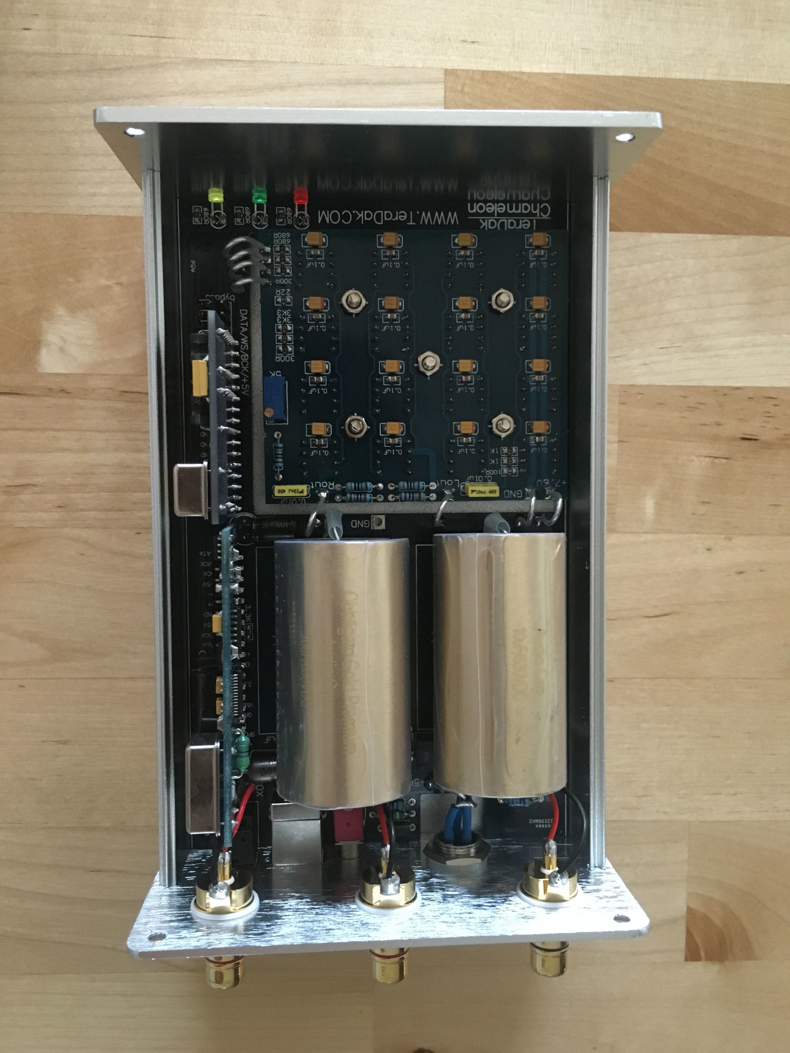
I double-checked and the Coax Spdif signal first travels down low cost wire to the board, then the selector switch, then to the low cost .01 filter cap in question, next 2 gold pins, 8 total solder points. Get that thing out of there .. get it all out of there! I suggest one solders the Coax Spdif wire direct from the RCA jack direct to pin 2 on the Pulse transformer. Check the picture 4 for details. Picasa Web Albums - Bill - Chameleon However if I were you Pat, I would remove the Pulse and solder this wire direct to your Lundahl input transformer. Run the primary "ground" to pin 2 and take advantage of the existing surface mount 75 ohm resistor. Hook the secondary to the existing pins 3 & 4. (If the Lundahl won't solder direct to pins 3 & 4 forgo the pliers and blowtorch and go with the duct tape).

I have had my Chameleon running at 9V DC for 24 hours without any sign of overheating, I have read where some guys prefer 10V DC with 16 TDA1543 DAC chips. As long as the chips are being cooled or heat-sinked apparently they can handle it. This on the other hand could be DIY folklore and you would be headed for a meltdown.

At the moment I have mine set at 7.85V DC with the yellow wire and really like the sound. I hear no benefit with the higher voltage as configured. However as I increase the voltage I have the suspicion the power supply is starting to sag even on the yellow wire. There is obviously a tipping point here somewhere, the question is who wants to be the one to push the limits. Woody you ready to sacrifice your Valab? (I have lots of extra 1543 DAC chips, I will experiment when time permits).

I have to say that Rhodes has me intrigued with using a Paul Hynes SR1-MR with a more heavy duty power transformer. Scottie ... more power!
 
Jan 16, 2010 at 9:09 PM Post #49 of 1,158
Bill,

Great idea going right to the Pulse. My Lundahl is staying the old VALAB. I have that set to perfection and will use it on another transport probably. don't want to mess with that baby.

What I may do is get the AudioNote's copper or silver and swap out in place of the stock Pulse.

Nice shot on the pic. That always helps.

Quote:

Originally Posted by Bill Allen /img/forum/go_quote.gif
Marcelnl- that's correct, I ripped that Russian cap out of there with a pair of pliers and blow torch. Seriously some transport's may pass DC, then you will want that blocking cap, however Steve suggests a .1uf cap in this case, not .01uf as installed.

Pat- poor guy you must Jonesing for the soldering iron, here i have something for you to try.

I double-checked and the Coax Spdif signal first travels down a cheap wire to the board, then the selector switch, then to the cheap .01 cap in question, next 2 gold pins, 8 total solder points. Get that thing out of there .. get it all out of there! Way to much monkey motion. I suggest one solders the Coax Spdif wire direct from the RCA jack direct to pin 2 on the Pulse transformer. Check the last picture for details. Picasa Web Albums - Bill - Chameleon However if I were you Pat, I would remove the Pulse and solder this wire direct to your Lundahl input transformer. Run the primary "ground" to pin 2 and take advantage of the existing surface mount 75 ohm resistor. Hook the secondary to the existing pins 3 & 4. (If the Lundahl won't solder direct to pins 3 & 4 forgo the pliers and blowtorch and go with the duct tape).

I have had my Chameleon running at 9V DC for 24 hours without any sign of overheating, I have read where some guys prefer 10V DC with 16 TDA1543 DAC chips. As long as the chips are being cooled or heat-sinked apparently they can handle it. This on the other hand could be DIY folklore and you would be headed for a meltdown.

At the moment I have mine set at 7.85V DC with the yellow wire and really like the sound. I hear no benefit with the higher voltage as configured. However as I increase the voltage I have the suspicion the power supply is starting to sag even on the yellow wire. There is obviously a tipping point here somewhere, the question is who wants to be the one to push the limits. Woody you ready to sacrifice your Valab? (I have lots of extra 1543 DAC chips, I will experiment when time permits).

I have to say that Rhodes has me intrigued with using a Paul Hynes SR1-MR with a more heavy duty power transformer. Scottie ... more power!


Jan 16, 2010 at 9:48 PM Post #50 of 1,158
Quote:

Originally Posted by Bill Allen /img/forum/go_quote.gif
.Woody you ready to sacrifice your Valab?
normal_smile .gif


I might well take that risk.., but only when my Chameleon arrives of course
wink.gif
, hmm but then there is the DC30 to cherish
frown.gif
 
Jan 16, 2010 at 9:53 PM Post #51 of 1,158
Bill, do you think a pulse transformer on the source act as sufficient protection for your mod?
 
Jan 16, 2010 at 10:00 PM Post #52 of 1,158
Hey Pat, I would not focus so much on the Audio Note wire. Certainly NOTHING multi-strand at all. The wire from V/H Audio is really superior stuff at a very decent price. Ask Bill Allen about it. He came to my place a while back and I showed him the difference just 1 foot of wire made (I was using A/N silver coated multi-strand wire on one input). No contest really. Bill wound up using the V/H stuff in his amp and preamp.
Tony in NM.
 
Jan 16, 2010 at 10:18 PM Post #54 of 1,158
Those transformers are what I was referencing.
And now I am think I am ready to go that way.

I did the straight from RCA to Transformer pin using 6n soft annealed silver. I wonder if the SPDIF read issues are being created by coming down to the board and through that switch. Been playing for a while and no read errors, no blasts of noise, better dynamics and/or quiet seems more quiet so less noise?

So I think using the AudioNote transformer will be an even better connection in that I will use one of the tranny's wire onto the RCA. Gotta get on and off fast with the iron. I can adhere the transformer with blu tac - all time favorite modding component.

RCAtoTrans.jpg


See also they move the .01 cap from the baords pins to the back of the board and the cap is of a different nature.

That fuzzy stuff on top is andti-EMI paper onto the clock.
 
Jan 16, 2010 at 10:26 PM Post #55 of 1,158
Pat do you think its worth swaping that smd 75 for a texas type thingy?
 
Jan 16, 2010 at 10:43 PM Post #56 of 1,158
there is only one way to tell.
from the drawing it looks like it only sets 75ohms in the incoming leg of the transformer then goes to ground. it looks like it can just be removed. The transformer is already at 75ohms on it's incoming leg and my output transformer on my CDP is 75ohms sooooo

Quote:

Originally Posted by Wood /img/forum/go_quote.gif
Pat do you think its worth swaping that smd 75 for a texas type thingy?


Jan 16, 2010 at 10:53 PM Post #57 of 1,158
Quote:

Originally Posted by Wood /img/forum/go_quote.gif
Bill, do you think a pulse transformer on the source act as sufficient protection for your mod?


DC (given that there would need to be a fair amount of current) would saturate the transformer making it perform poorly (square waves would suffer and get spikey), so I'd not use a transformer without DC blocking cap in case the source could/does send out DC.
 
Jan 16, 2010 at 10:57 PM Post #58 of 1,158
Quote:

Originally Posted by PatOMalley /img/forum/go_quote.gif
there is only one way to tell.
from the drawing it looks like it only sets 75ohms in the incoming leg of the transformer then goes to ground. it looks like it can just be removed. The transformer is already at 75ohms on it's incoming leg and my output transformer on my CDP is 75ohms sooooo


I plan on trying that one too, a quick noise free fast resistor in that spot should help keeping performance up imho (less so than the obvious candidates).
 
Jan 16, 2010 at 11:33 PM Post #60 of 1,158
I vote for giving these transformers a try, I know Phill once talked about getting one, wonder if he ever did? I believe they will sell individual samples for $15 if memory serves me correctly. Notice they will handle up to 192 khz.

The stock pulse only goes up to 96khz, I am now going to bypass it now and see how it sounds.

Scientific Conversion, Inc. - Transformers and Inductors
 

Users who are viewing this thread

Back
Top