Chameleon DAC listening and modifications

Jan 10, 2010 at 12:58 PM Post #16 of 1,158
Swapped the Sanyo with a 6800pf styro in the same place, no hiss now, will give it some time and see.
 
Jan 12, 2010 at 3:04 AM Post #19 of 1,158
Gentlemen,

Rolling through 400 hours on my bone stock pre-production Chameleon and while I would say the DAC is ready for prime time at 200 hours, at 400, there is just more there ... there!

Bad news is I still sense a lack of dynamics and bass so I decided to up the voltage to 9 VDC to the DAC chips. Guess what, turning the variable resistor inside the DC-30 power supply only netted me 8.7 volts no matter how much I kept turning.

Houston we have a problem!!!

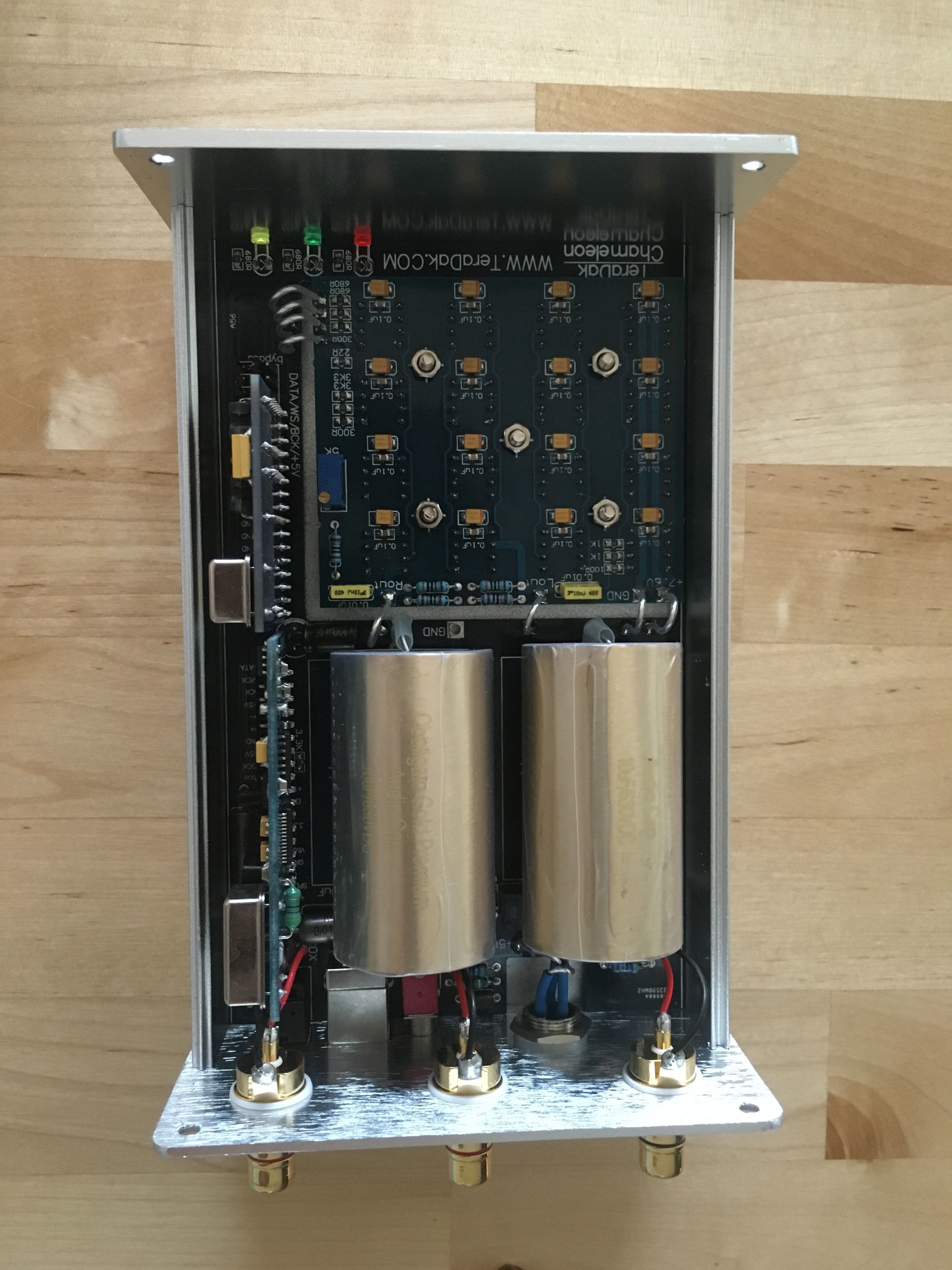
The power supply is running out of gas trying to drive the 16 DAC chips. We need more amps, put more coal to the fire! Well fortunately there is an unused 15.5 VAC tap on the R-Core transformer. Simple fix ... I removed the "Blue" 11.5 VAC wire and soldered on the "Yellow" 16 VAC wire. (The transformer incorrectly reads 9V & 12VAC with 2.5A output at 12V, I suspect they mean 2.5A at 15.5 V).

My math shows with 16 DAC chips we need right around 2 amps of current. Obviously with the 12VAC tap we are running a bit shy of that mark. With the 8 DAC chips of the Valab this may have been fine but not with "Big Dog" Chameleon. i set the DAC input voltage to 7.85 VDC and it stayed the same even with the yellow wire soldered in place but please double check.

Botta Bing, Botta Boom!

The Chameleon is now hitting on all cylinders, very nice drive and dynamics. I venture to say, even in stock form, the Chameleon now outperforms my fully modded Valab on just about every measure. Sounds very open and balanced even with the stock Wima coupling caps. Great news for you non-solder heads.

Excellent job Michael.

Note: For those of you who already have a Chameleon DAC in the mail, double check to make sure the 15.5 VAC yellow wire from the transformer is soldered to the board inside the DC-30.

(Stay tuned as I will play with upping the voltage even beyond the so-called maximum 8 VDC limit of the TDA 1543 DAC chip. For now this falls in the "don't try this at home category". Stick with 7.85VDC max input until full testing is complete).

Peace!
 
Jan 12, 2010 at 5:01 PM Post #20 of 1,158
Bill,

Nice discovery there, let us know how it works out.

Does anything else have to be changed, in the Chameleon when adjusting the voltages to the dacs, such as iv, trimmer pot etc?
 
Jan 12, 2010 at 5:59 PM Post #21 of 1,158
Quote:

Originally Posted by Wood /img/forum/go_quote.gif
Bill,

Nice discovery there, let us know how it works out.

Does anything else have to be changed, in the Chameleon when adjusting the voltages to the dacs, such as iv, trimmer pot etc?


When you change the voltage to the DAC chips the output needs to be ajusted again. Take a 0dB sinewave and burn it on CD. Play it through the chameleon, get your multimeter (if you don't have a scope) and use the trimmer on the DAC board to get the highest output voltage. I'm not sure if the output voltage differs from the Valab DAC but it is probably around 2.0V AC.
 
Jan 12, 2010 at 6:51 PM Post #22 of 1,158
Thanks rhodes54, didnt fancy changing iv resistors everytime I spin the trimmer to the dacs. Will give it a go on the Valab for now.
 
Jan 12, 2010 at 8:01 PM Post #23 of 1,158
Rhodes- Thanks for Vref output voltage adjustment tip.

I just received and email from Michael and he is a tad concerned with the extra heat generated hooking to the yellow 12V AC tap. I found that while "yes" the aluminum case of the DC-30 does get quite a bit warmer ... it is not "hot" to the touch. (I.E. I can keep holding my finger on the case).

However ... Michael was more concerned with the 1/4 watt resistor's for the TL431 voltage regulators holding up under this current load. There are 2 TL431 and 2 output transistors inside the DC-30, one for 5V output to the receiver board and one 7.55V for the DAC chips. Adjustable via the blue variable resistors, reference Pat's picture on page one. Looking at the PDF it looks like Michael has the DC-30 set up for Shunt Regulation.
http://www.fairchildsemi.com/ds/TL%2FTL431.pdf

Damn, there never seems to be a free lunch when it comes to electonic's.

For now I am enjoying the increased bass dynamics and slam of my "Yellow Wire Mod" on the Chameleon. However I am keeping a close eye on those little blue resistors in questions. So far no discoloration or signs of overheating. I will keep everyone posted on what the final fix will be.

Let's just hope in the interim that my Chameleon doesn't turn to a smoke color. But hey, this is the grey area that us modder's are forced to live in. No pain ... no gain!

The important thing is that the Symbiotic relationship between the designer and modder's is hard at work. This on the other hand is "very cool"!!!
 
Jan 12, 2010 at 9:34 PM Post #24 of 1,158
Heh heh Nice to see you back in the thick of it Bill.


But have to disagree with you on one point.

'Damn, there never seems to be a free lunch when it comes to electonic's.'

Lets not forget your dir9001 mod!!
 
Jan 13, 2010 at 3:49 AM Post #27 of 1,158
Probably because everyone is a little gun shy after the last TeraDak Chameleon thread was shut down due to a rule infraction in organizing the group buy on the initial units.

Michael the owner of TeraDak has informed me that he will have a website up and running within 10 Days. I will add a link when it appears on the net.

For now you can email questions direct to Michael at: teradak888@hotmail.com
 
Jan 13, 2010 at 4:23 AM Post #28 of 1,158
Bill, watch you dont turn the varistors past the point of no return, there is only a certain number of r turns on the pot and once you go past this you cant turn it back, or rather you can turn it back but it wont do anything
 
Jan 13, 2010 at 8:48 PM Post #30 of 1,158
Quote:

Originally Posted by Bill Allen /img/forum/go_quote.gif
Probably because everyone is a little gun shy after the last TeraDak Chameleon thread was shut down due to a rule infraction in organizing the group buy on the initial units.

Michael the owner of TeraDak has informed me that he will have a website up and running within 10 Days. I will add a link when it appears on the net.

For now you can email questions direct to Michael at: teradak888@hotmail.com


it's up , just not yet filled with content ;-)
TeraDak

Bill, I'm not sure I follow your calculated power requirement of 2.0A. 16*80 mA for the TDA 1543 alone eats up 1.2- 1.3 A, any PSU in the gear I build would have at least twice but preferably three times as much oomph as strictly required.
Am I missing something here?
 

Users who are viewing this thread

Back
Top