Chameleon DAC listening and modifications

Jan 14, 2010 at 12:54 AM Post #31 of 1,158
Marcelnl - My math show's around 1 amp required for just the 16 DAC chips and yes at least 1 amp for headroom is minimum in my book too.

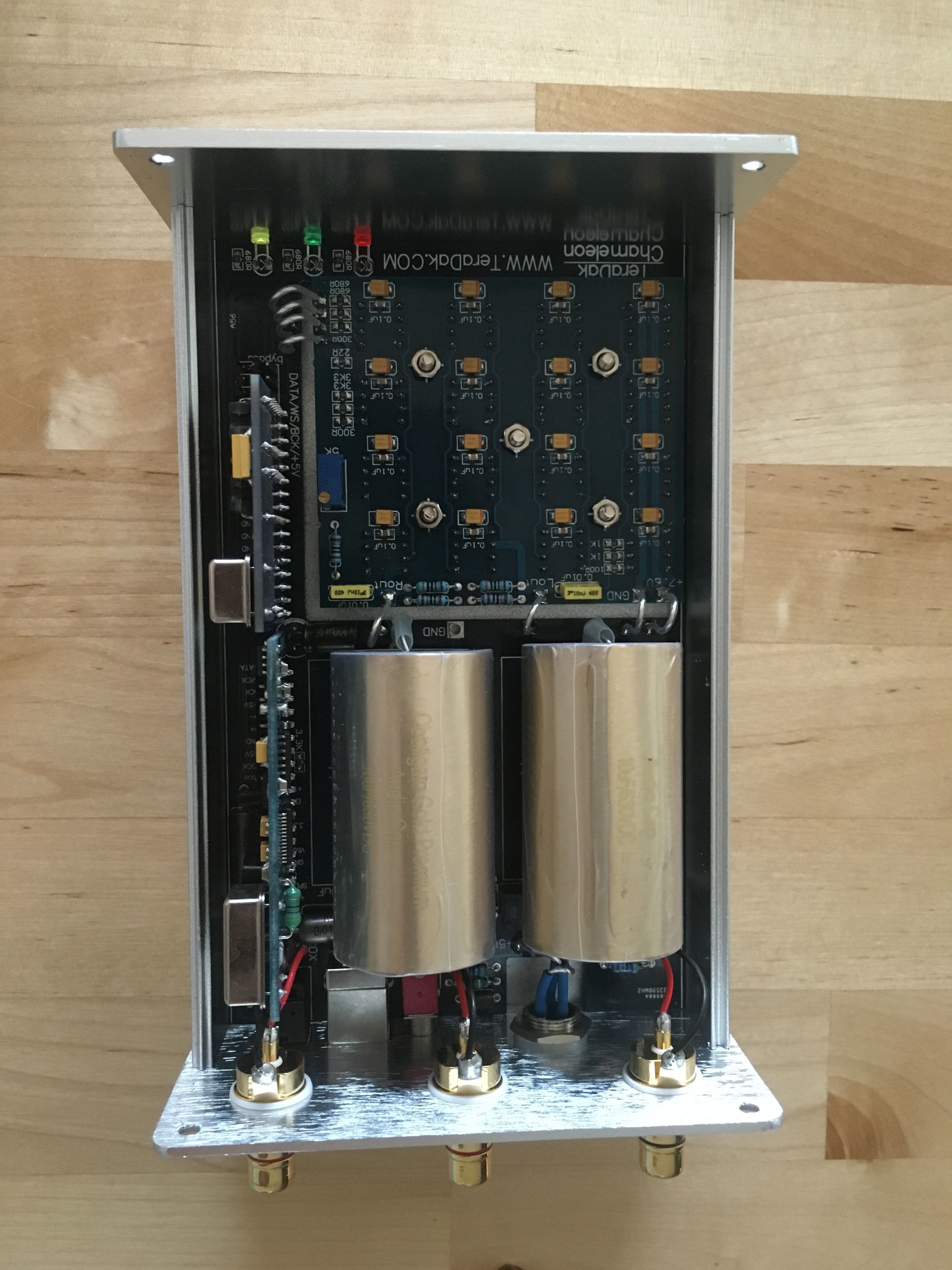
The R-Core transformer inside the DC-30 can supply 2.5 amps with the yellow 12V AC tap. I prefer the extra current it provides at the expense of more heat. I found that by simply installing taller feat under the DC-30 provided a "substantial" reduction of heat to the aluminum case. Now it is just warm to the touch.

I talked to Michael and his plan is to continue using the 9V AC blue wire for the production Chameleon DAC. This keeps everything within a safe margin no matter what worldwide voltage is being used. I agree.

However for us solder heads he suggests as long as we keep the case cool there should be no long term issues using the "Yellow Wire Mod." This is not exactly a green light from the designer, more like a flashing yellow light.

Proceed with Caution!
 
Jan 14, 2010 at 1:44 AM Post #32 of 1,158
why not just replace the questionable resistors with 1/2 watt? this should be easy enough.
 
Jan 14, 2010 at 1:48 AM Post #33 of 1,158
Quote:

Originally Posted by Bill Allen /img/forum/go_quote.gif
However I am keeping a close eye on those little blue resistors in questions. So far no discoloration or signs of overheating.


Bill, do you have access to an Infrared gun? I'm certain it will tell you if those resistors are under stress...


Norm
 
Jan 14, 2010 at 7:05 AM Post #34 of 1,158
Is'nt the simplest way is to measure the voltage drop over the resistor and calc the current.
Now calc the power used and you know whether they are at risk.

Bill, thanks for confirming my thoughts, I'm not sure I'm with you on the heat generated as surely the transformer will not run hotter at its still operating at its design limits and delivering the same power. For perhaps the reg and for the resisitors the power reserve may be on the edge and heat may be an issue.
 
Jan 14, 2010 at 7:16 AM Post #35 of 1,158
many decent DMM have a heat sensor as well. no need to get all robocop on it
biggrin.gif
 
Jan 14, 2010 at 8:04 PM Post #36 of 1,158
guess mine is not decent ;-)

Bill, I'm with you it is just that I usually try to have some more safety margin as transformer specs frequently show the highest output power before they evaporate....
I plan on putting the dac board in my own enclosure as I usually end up with my gear looking like a nuclear plant and unable to close the lid anyway, so cooling air can be handled.

I'll start by using the 12 V wire before trying lipo batteries and some capacitance, I'm a believer in overall capacity in a PSU since my ' little' Le Monstre class A amp.

Worst case the voltage reg goes as it'll have to eat up to much heat but without checking the specs I am not too afraid of that, the resistors will be replaced anyway.
 
Jan 14, 2010 at 10:23 PM Post #37 of 1,158
mine's finally on the way, should have it here in a week or so. Can't wait to try it out.
ksc75smile.gif
 
Jan 14, 2010 at 11:17 PM Post #38 of 1,158
All good ideas but I installed larger feet, quit worrying about the extra heat, and moved on to ...

The BAMM! (Bill Allen Madman Mod)

The Chameleon turned out to be a much easier DAC to Mod compared to the Valab thanks to TeraDak's total redesign. The ground plane is utter “simplicity”, which I of coarse further simplifed. And while I appreciated the extra room to install big dog coupling caps, the space is still insuffecient for my NG (Next Generation) Jupiter 4.7uf caps. Damn! If only the case was as wide as the previous Valab DAC then 4.7uf Boutique Caps would fit perfectly. As is, the space only provides 2.5" L by 3" W and 1.8"H. However if I remove the input board then the Jupiter's "will" fit inside. (And I will be doing just this in the near future when I run I2S direct from the Pace Car to the I2S jumper pins, more on this later).

I bypassed the Spdif selector switch by unsoldering one leg of the Russian input cap and soldering it direct to the RCA jack. It works so perfect, it was as if it was designed that way. Humm! It does however beg for a better quality cap and perhaps a higher quality input transformer ... that is if one wants to go all the way with Spdif.

I removed all 16 little 10uf surface mount caps and installed 16 each 47uf Blackgate FK caps on the DAC chips. There are thoughtfully open holes for doing just this for 12 of the 16 DAC chips. For the final 4 near the front you have to bend the legs and solder direct like we did on the Valab.

I soldered the coupling caps direct to the output of the DAC chip, then soldered the I/V resistor to this same leg. I soldered the other end of the (200 ohm) I/V resistor & RCA ground wires direct to the ground input on the DAC chip board. (This is as direct a connection as you can get … a thing of beauty in my eyes). Interesting, the way Michael laid out the board the filter circuit is still in play. One would have to cut the trace or remove the brown chiclet looking caps to deactivate the filter. I decided to leave mine alone ... for now!

How does it sound? Only time will tell but preliminary results are very positive.

Here are the pictures of The BAMM process.
Picasa Web Albums - Bill - Chameleon
 
Jan 15, 2010 at 7:56 AM Post #39 of 1,158
I wonder if Michael would be willing to sell the board with the essential electronics only (w/o the PSU, and caps resistors etc) for folks that want to one step further than modding the heck out of the complete thing.....anything shy of designing my own circuitboard.

As Bill already indicated running out of space is pretty much guaranteed when modding a device, adding a decent PSU and all those caps definitely will warrant a decent enclosure.
 
Jan 15, 2010 at 9:40 PM Post #40 of 1,158
Bill, cant see to clearly but the blackgates look like reverse polarity to how they are on the Valab.
 
Jan 16, 2010 at 1:36 AM Post #41 of 1,158
Quote:

Originally Posted by marcelnl /img/forum/go_quote.gif
I wonder if Michael would be willing to sell the board with the essential electronics only (w/o the PSU, and caps resistors etc) for folks that want to one step further than modding the heck out of the complete thing.....anything shy of designing my own circuitboard.

.


I am sure this is not possible. I did ask Mchael a smiliar question in the past and was told no. The reason is because Teradak have their PCB stuffed by an outside company and there is very little flexibility stuffing the PCB with parts supplied by TerDak.
 
Jan 16, 2010 at 2:02 AM Post #42 of 1,158
Quote:

Originally Posted by Bill Allen /img/forum/go_quote.gif
Marcelnl - My math show's around 1 amp required for just the 16 DAC chips and yes at least 1 amp for headroom is minimum in my book too.

However for us solder heads he suggests as long as we keep the case cool there should be no long term issues using the "Yellow Wire Mod." This is not exactly a green light from the designer, more like a flashing yellow light.

Proceed with Caution!


This Yellow wire mod is a keeper. I noticed more music detail overall... As Bill mentioned, it does get lttle warmer. About 35C or 109F on the surface. My advise is to either raise the feet of the DC-30W or stand the DC-30W on its side so the bottom is on its side. Drilling extra holes on the side of the case is also a good idea.
 
Jan 16, 2010 at 9:20 AM Post #43 of 1,158
Well my Chameleon BAM Mod is starting to sound "really ... really good" thanks in part to Woody and Steve Nugent.

Yup I had those blackgate FK's in backwards, "Huge" improvement ... Thanks Woody!

I also removed that silver colored Spdif input cap, replaced it with a solid silver wire. "Big" improvement ... Thanks Steve!

As Norm states, the yellow wire mod also a keeper, I have 2 DC-30's (one of them stock) and the yellow wired one is clearly superior sounding. Yes more betta detail.
 
Jan 16, 2010 at 1:45 PM Post #44 of 1,158
Am I right in assuming you ripped out the input s/pdif signal cap caus' your transport has DC blocking measures?
(not sure if that holds true for all sources)
 
Jan 16, 2010 at 4:25 PM Post #45 of 1,158
Bill,

The cap on the board is only for the Toslink incoming connection. Or so it looks on the drawing. But that cap is tied to the negative of the transformer that bring it to ground. So a jumper is needed but you are only removing that cap for the benefit of the lighted wire.


Quote:

Originally Posted by Bill Allen /img/forum/go_quote.gif
Well my Chameleon BAM Mod is starting to sound "really ... really good" thanks in part to Woody and Steve Nugent.

Yup I had those blackgate FK's in backwards, "Huge" improvement ... Thanks Woody!

I also removed that silver colored Spdif input cap, replaced it with a solid silver wire. "Big" improvement ... Thanks Steve!

As Norm states, the yellow wire mod also a keeper, I have 2 DC-30's (one of them stock) and the yellow wired one is clearly superior sounding. Yes more betta detail.


Users who are viewing this thread

Back
Top