So in the course of last 15 hours or so I see there was a flurry of activities on this post and too bad I missed all that excitment... I just got caught up now. Here is my comment on some fo things that was asked.
- After A/B DC-30W blue vs yellow wire mod the best way to describe it is like going from a computer power cord to a decent power cord. I was listening to one of my favourite Canadian jazz singer Diana Panton (
DianaPanton.com | Canada's Rising Jazz Star) with the yellow wire mod her voice went from a young adult to a mature woman - I still can't believe it.... I will most likely drill some small holes to both sides of the chassis and raise the legs. Another thing that is making me wonder is to use better DC cable between DC-30 and Chameleon since we have proven that blue wire was current starving the DAC.
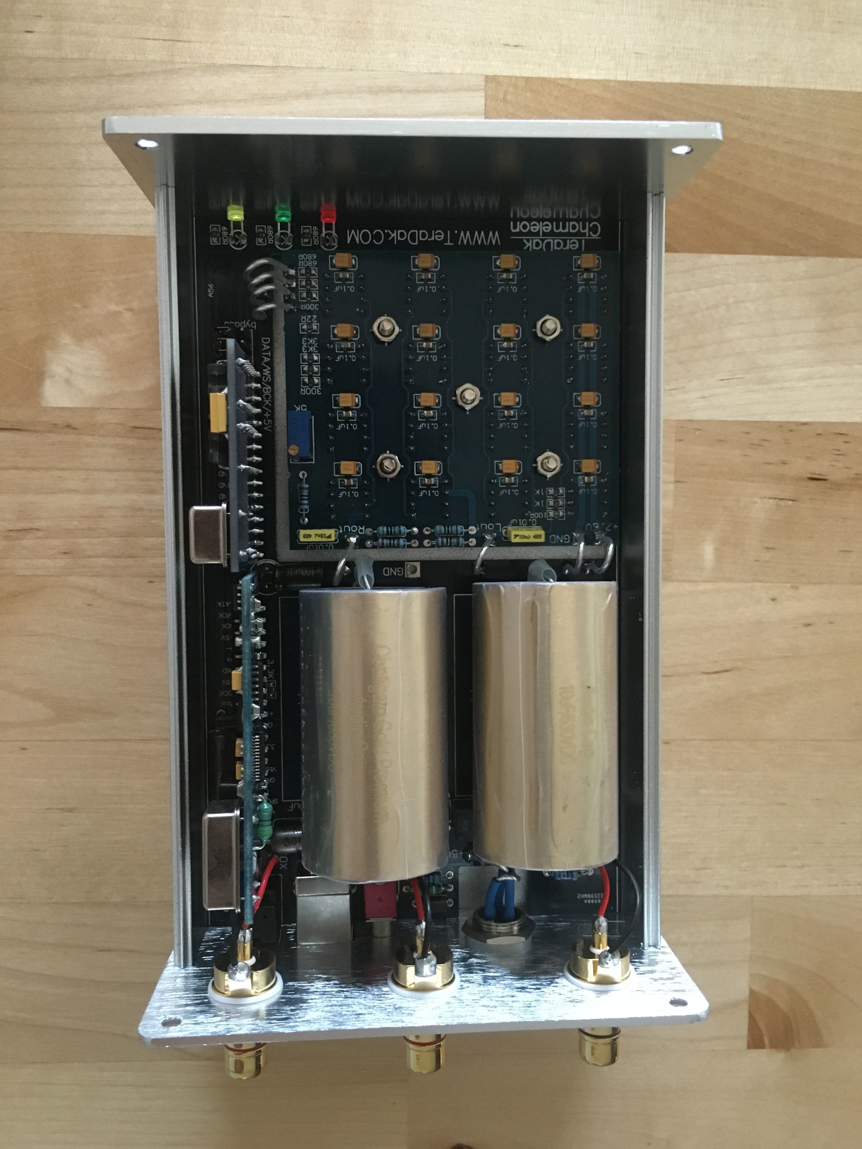
- Bill, the 0.1uF cap you refered to on the back of Pat's clock board, I believe it will be there on all the clock boards Michael is shipping. It is basically a coupling cap between the output of transformer and the clock chip, I think Michael used it to cancel any start-up noise. Michael actually have similar cap in the pre-production boards you and I have but it is on the wrong side of the transformer.
- I/V resistor is that blue resistor Bill mentioned, however, when I pulled my off circuit I found them to measure 160R... Accordig to Michael the ideal value is 175R which is hard to find. I have 172.5R after manually matching two 330R in parallel
- Bill/Pat, both of you have removed that 0.01uF slver mica from the ouput. I will be curious to hear what you think if you added a similar value teflon cap there instead. As I mentioned, I currently have Vishay MKP there and found th sound uplifting...
- Pat, you mentioned looking for better transport? Can you share what are you looking at? I on the other hand, am going down the path of looking for a decent DVD/CDP player as transport new/old ...


")


