


Mahdi8
100+ Head-Fier
- Joined
- Apr 27, 2013
- Posts
- 393
- Likes
- 22
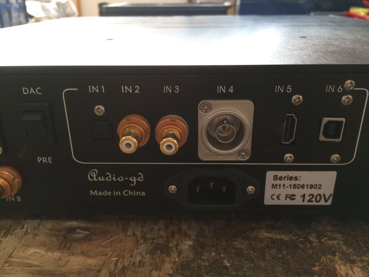
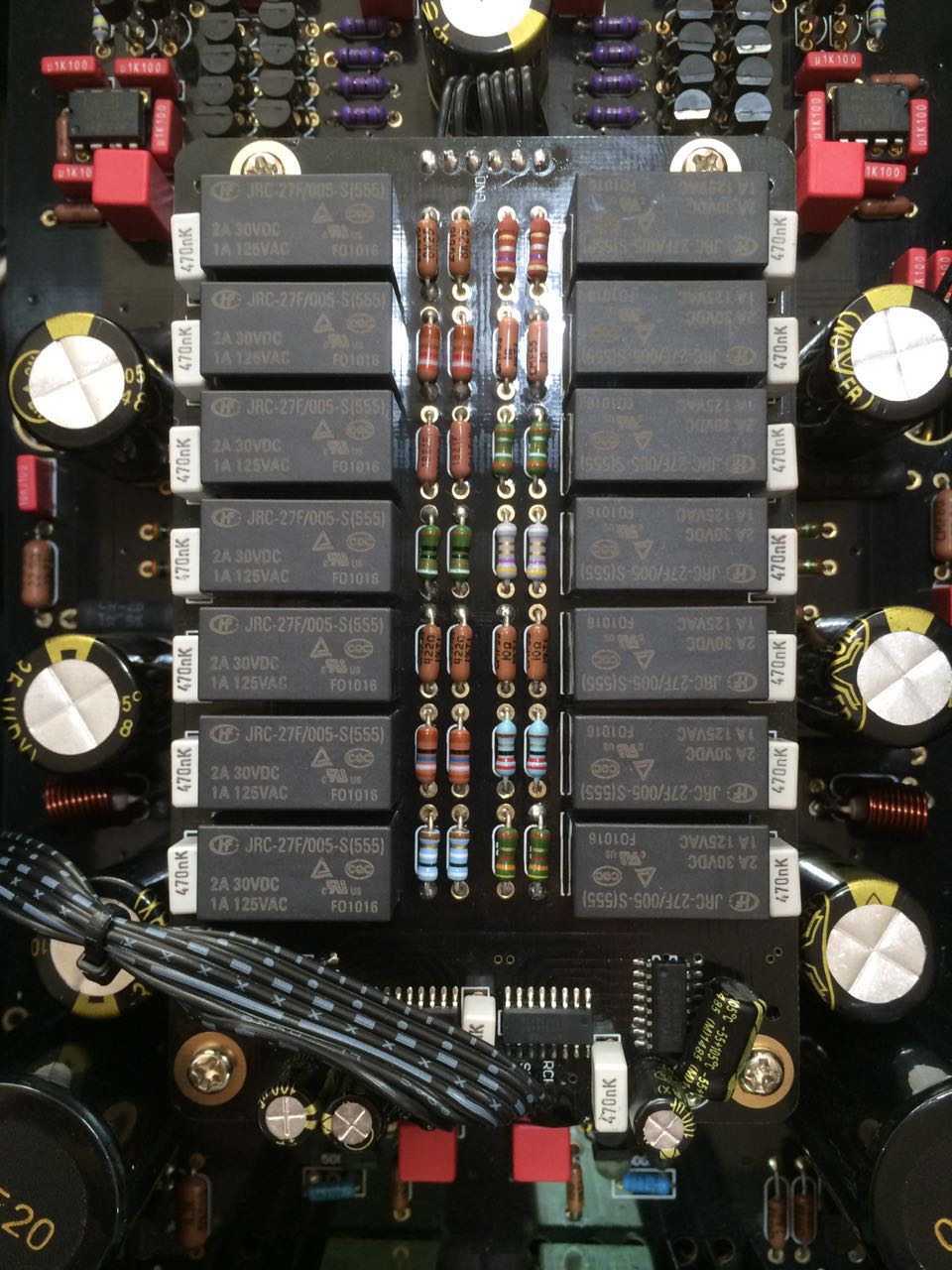
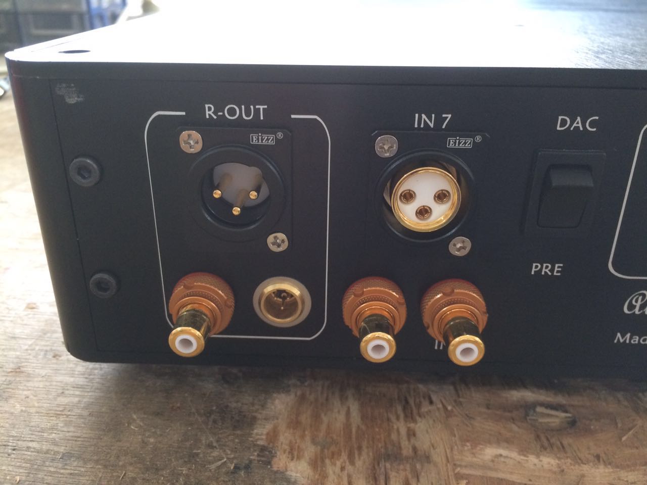
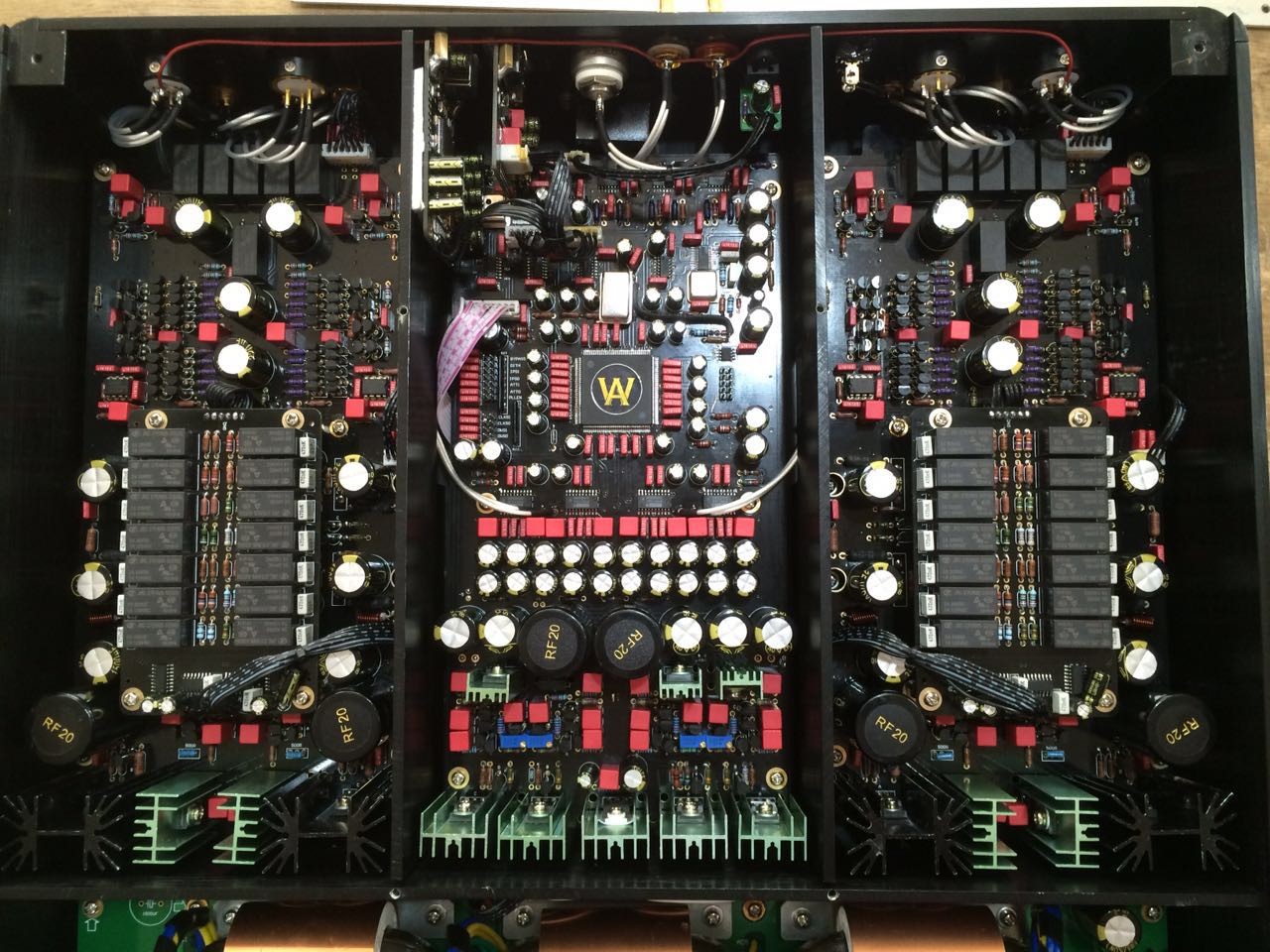
I've just finished putting hdmi kit on my ref7 not 2 hours ago another Melbournian what's the odd that happening ") looking at the board of master 11 doesn't look like it's been labeled thoroughly like ref7 might be better to ask king wa.
looking at the board of master 11 doesn't look like it's been labeled thoroughly like ref7 might be better to ask king wa.
looking at the board of master 11 doesn't look like it's been labeled thoroughly like ref7 might be better to ask king wa. 