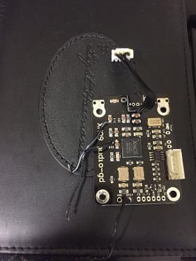
Audio-gd DI-U8 Audio Interface (Xmos U8)
Feb 4, 2016 at 1:24 PM Thread Starter Post #1 of 112

InsanityOne

500+ Head-Fier
Joined
Jan 30, 2014
Posts
517
Likes
74
Hello Head-fi'ers,
 
I haven't seen anyone talking about the new Audio-gd DI-U8 Audiointerface. Supposedly it is limited to 150 units so hopefully someone from Head-Fi can pick one up for a review or some comparisons.
 
SOURCE: http://www.audio-gd.com/Pro/dac/DIU8/DIU8EN.htm
 
Here are the specs:
 
Power supply
100-130V / 210-240V 
 

Output Level
 
0.5 Vp-p (at 75 Ohms)  @ SPDIF
3.3V p-p (25MA) @ I2S
Input Sensitivity
0.5 Vp-p(75 Ohms, Coaxial)
19 dBm at Optical
USB1.1 ,USB2.0 ,USB3.0 (Full Speed, High Speed, Class2)
 
Support Sampling (Input) 
USB mode: 44.1kHz, 48kHz, 88.2kHz, 96kHz, 176.4kHz, 192kHz ,352.8kHz ,384kHz
 Coaxial mode: 44.1kHz, 48kHz, 88.2kHz, 96kHz, 192kHz 
Optical mode: 44.1kHz, 48kHz, 88.2kHz, 96kHz, 
 
Support Sampling (output) 
USB to I2S mode : 44.1kHz, 48kHz, 88.2kHz, 96kHz, 176.4kHz, 192kHz  ,352.8kHz ,384kHz (Up to 32bit)
Coaxial to I2S mode: 44.1kHz, 48kHz, 88.2kHz, 96kHz, 192kHz  (Up to 24bit)
USB to coaxial mode : 44.1kHz, 48kHz, 88.2kHz, 96kHz, 176.4kHz, 192kHz  (Up to 24bit)
Coaxial to Coaxial : 44.1kHz, 48kHz, 88.2kHz, 96kHz, 192kHz  (Up to 24bit)
 
Power Consumption
8W
 
Package Weight
Approximately 2.5KG
 

Dimensions
 
W180 X L220 X H55 (MM, Fully aluminium ) 
Accessories
USB cable                X1


And some photos:


Conclusion:
 
I would be very interested to see how this DI-U8 stacks up against the Gustard-U12, Breeze DU-U8 and the Melodius MX-U8. I have been considering getting a conversion interface but I am not sure which one is the best. (Not counting the Empirical Audio Off-Ramp 5)
 
- InsanityOne 
darthsmile.gif
 
 
Feb 4, 2016 at 3:10 PM Post #3 of 112
  Hello Head-fi'ers,
 
I haven't seen anyone talking about the new Audio-gd DI-U8 Audiointerface. Supposedly it is limited to 150 units so hopefully someone from Head-Fi can pick one up for a review or some comparisons.
 
SOURCE: http://www.audio-gd.com/Pro/dac/DIU8/DIU8EN.htm
 
Here are the specs:
 
Power supply
100-130V / 210-240V 
 

Output Level
 
0.5 Vp-p (at 75 Ohms)  @ SPDIF
3.3V p-p (25MA) @ I2S
Input Sensitivity
0.5 Vp-p(75 Ohms, Coaxial)
19 dBm at Optical
USB1.1 ,USB2.0 ,USB3.0 (Full Speed, High Speed, Class2)
 
Support Sampling (Input) 
USB mode: 44.1kHz, 48kHz, 88.2kHz, 96kHz, 176.4kHz, 192kHz ,352.8kHz ,384kHz
 Coaxial mode: 44.1kHz, 48kHz, 88.2kHz, 96kHz, 192kHz 
Optical mode: 44.1kHz, 48kHz, 88.2kHz, 96kHz, 
 
Support Sampling (output) 
USB to I2S mode : 44.1kHz, 48kHz, 88.2kHz, 96kHz, 176.4kHz, 192kHz  ,352.8kHz ,384kHz (Up to 32bit)
Coaxial to I2S mode: 44.1kHz, 48kHz, 88.2kHz, 96kHz, 192kHz  (Up to 24bit)
USB to coaxial mode : 44.1kHz, 48kHz, 88.2kHz, 96kHz, 176.4kHz, 192kHz  (Up to 24bit)
Coaxial to Coaxial : 44.1kHz, 48kHz, 88.2kHz, 96kHz, 192kHz  (Up to 24bit)
 
Power Consumption
8W
 
Package Weight
Approximately 2.5KG
 

Dimensions
 
W180 X L220 X H55 (MM, Fully aluminium ) 
Accessories
USB cable                X1


And some photos:


Conclusion:
 
I would be very interested to see how this DI-U8 stacks up against the Gustard-U12, Breeze DU-U8 and the Melodius MX-U8. I have been considering getting a conversion interface but I am not sure which one is the best. (Not counting the Empirical Audio Off-Ramp 5)
 
- InsanityOne 
darthsmile.gif
 

Thank you for starting this thread. I own just about one of every DDC, including the DIU8. I'll have extra XMOS modules for the DIU8 on monday, but will be modding my module this saturday with Crystek 957's.
I'll be happy to post results to this thread about my findings between the U12, U12 modded, Pro3A, breeze, melodious, etc etc.
 
Feb 4, 2016 at 3:23 PM Post #4 of 112
  Thank you for starting this thread. I own just about one of every DDC, including the DIU8. I'll have extra XMOS modules for the DIU8 on monday, but will be modding my module this saturday with Crystek 957's.
I'll be happy to post results to this thread about my findings between the U12, U12 modded, Pro3A, breeze, melodious, etc etc.

Interesting, I assume that the Crystek 957's you are talking about are THESE? If so, which frequency are you using and what improvements do you expect over the stock configuration? I tried to find singular XMOS U8 chips for sale as well, but didn't have any luck. Where did you get yours from?
 
Also, it might be a neat thing to do if you posted a modding guide or some modding instructions in this thread when you have completed the process. Others might wish to do the same thing!
 
Oh, and what upgrades did you do to your U12? I don't think I have heard about that.
 
- InsanityOne 
biggrin.gif
 
 
Feb 4, 2016 at 6:31 PM Post #5 of 112
My u12 has modified lvds to be compatible with HDMI i2s for audio-gd pin out. The u12 is otherwise not compatible with audiogd gear without this mod.
Also, I upgraded the lm317d2t 5V regulator with an ultra low noise regulator instead. Currently have a 5uV noise regulator but switching it up to a 1.6uV regulator.
Also upgraded to low ear 25v 3300uF panny caps. Gutted the ac transformer and ac circuit and wired in a 2.5mm/5.5mm DC inlet plug in replacement of the ac mains. Now a low noise linear power supply can power this u12 at 7V. A teradak dc30W is what I have been using since it's easy to change voltage output.
I added some rf/emi absorbent film from 3M to the noisy ic's. Ab5050s by 3M. Also upgraded the clocks to crystek 957 clocks mounted on concerted dip14 boards, and mounted dip14 4pin sockets. The original crystals can be replaced easily for comparison.
I'm actually selling my gustard for pretty cheap. That's because my modding of the coax transformer went bad and now the coax output doesn't work. But for me, not a big deal since I use i2s HDMI with my audio-gd gear. I and keeping my diu8 as it has all the input and outputs I need.
 
Feb 4, 2016 at 11:01 PM Post #6 of 112
My u12 has modified lvds to be compatible with HDMI i2s for audio-gd pin out. The u12 is otherwise not compatible with audiogd gear without this mod.
Also, I upgraded the lm317d2t 5V regulator with an ultra low noise regulator instead. Currently have a 5uV noise regulator but switching it up to a 1.6uV regulator.
Also upgraded to low ear 25v 3300uF panny caps. Gutted the ac transformer and ac circuit and wired in a 2.5mm/5.5mm DC inlet plug in replacement of the ac mains. Now a low noise linear power supply can power this u12 at 7V. A teradak dc30W is what I have been using since it's easy to change voltage output.
I added some rf/emi absorbent film from 3M to the noisy ic's. Ab5050s by 3M. Also upgraded the clocks to crystek 957 clocks mounted on concerted dip14 boards, and mounted dip14 4pin sockets. The original crystals can be replaced easily for comparison.
I'm actually selling my gustard for pretty cheap. That's because my modding of the coax transformer went bad and now the coax output doesn't work. But for me, not a big deal since I use i2s HDMI with my audio-gd gear. I and keeping my diu8 as it has all the input and outputs I need.

 
Phew! Sounds like you did quite a bit of work to the U12! Good luck with the sale! (Sorry to hear about the Coax Output though.) But since you are selling the U12 I would assume that you believe the DI-U8 to be the better performer? I'll be excited to hear your impressions before and after you install the Crystek 957's.
 
- InsanityOne 
k701smile.gif

 
Feb 5, 2016 at 10:28 AM Post #7 of 112


tricky to do, but everything works well!
 
I used some DIP14 extra long leads and bent them into the proper shape. Clipped the ends flush and hot air soldered the dip14 sockets first, then the 957's next. Added Murata GRM2195C1H103FA01D with a tight 1% tolerance for bypass capacitors. Sounds niiiiiiiice. :D definitely my favorite DDC now! detail retrieval is very good! 
 
Feb 5, 2016 at 10:31 AM Post #8 of 112
   
Phew! Sounds like you did quite a bit of work to the U12! Good luck with the sale! (Sorry to hear about the Coax Output though.) But since you are selling the U12 I would assume that you believe the DI-U8 to be the better performer? I'll be excited to hear your impressions before and after you install the Crystek 957's.
 
- InsanityOne 
k701smile.gif

I just finished my DIU8 crystek 957 install...now i'm going to remove the belleson regulator from the U12 and install the AckoDac AKR75 5v regulator. But the U12 is still up for sale. It is strictly DC powered and will upload some photos of it soon.
 
Feb 5, 2016 at 11:18 AM Post #9 of 112
  I just finished my DIU8 crystek 957 install...now i'm going to remove the belleson regulator from the U12 and install the AckoDac AKR75 5v regulator. But the U12 is still up for sale. It is strictly DC powered and will upload some photos of it soon.

 
Sweet! That sounds great! How would you rate the difficulty of doing all of this? Say, in terms of someone who has never soldered / does not solder very often?
 
- InsanityOne 
tongue.gif

 
Feb 5, 2016 at 11:40 AM Post #10 of 112
Well... hahaha. Funny you ask.
 
Kingwa wouldn't even sell me replacement xmos modules until I could show him I was capable to remove the XMOS board from the DIU8. quite frustrating since you DON'T NEED TO REMOVE IT to do the mod. :wink:
 
but I did.
 
just so I could get a backup board in case something did go wrong.
 
 
Also, those stock crystals are cheapo 80cents each or something.  I removed them with a hot air gun, I recall the solder being liquid around 200C. Pulled them from the board with tweezers.
cleaned up the board. Used SRA low temp solder paste. Set my airgun to 170C. while it was warming up I added some small drops of solder paste to the modified dip14 with long leads...
 

I clipped all the leads except the outer 4 corners. Then bent the pins accordingly with needle nose pliers to align perfectly to the orignal traces on the xmos module. (this is very tricky and requires a lot of patience, and although I didn't need extras, it's wise to order maybe 4 of these in case you mess one up) Notice that the 957's sit a slight angle, as I tried to get them slightly apart so the top converter boards should not touch or be too tight.  I could of done a better job, but overall am quite happy with how it sounds! 
 
 
to cut this short. It's NOT an easy mod, but quite worth it if you're handy with soldering. I found it important that this mod is done with solder paste and hot air gun with small precise tip.
this xmos board will accept crystals that are TRIstate. so the fancy micro NDK's technically could work...but my first attempt was those buggers, and I layed down copper traces to extend the contact points.IT DIDN'T work, so I scrapped that idea. I should of bought more NDK's since those buggers can get overheated WAY too easy.  The crystek 957's seem to be slightly easier than ndks. I wish there was a crystal that was this size for a quick swap. 
 
anyhow, I would say this isn't for everyone.  I got a lot of gear to do this mod. I'm not an expert. But anyone who has had experience in solder paste and hot air guns may feel comfortable doing this.
 
https://www.youtube.com/watch?v=2Z7nCAxS2Rg
 
watch that for some idea of what to expect.
he actually installs an oscillator on a keyboard. But not exactly the same thing that needs to happen with the DIU8 and dip14 sockets.
kinda a pain DIY project. But i'm quite happy I worked out so well!
 
Feb 5, 2016 at 12:51 PM Post #11 of 112
  Well... hahaha. Funny you ask.
 
Kingwa wouldn't even sell me replacement xmos modules until I could show him I was capable to remove the XMOS board from the DIU8. quite frustrating since you DON'T NEED TO REMOVE IT to do the mod. :wink:
 
but I did.
 
just so I could get a backup board in case something did go wrong.
 
 
Also, those stock crystals are cheapo 80cents each or something.  I removed them with a hot air gun, I recall the solder being liquid around 200C. Pulled them from the board with tweezers.
cleaned up the board. Used SRA low temp solder paste. Set my airgun to 170C. while it was warming up I added some small drops of solder paste to the modified dip14 with long leads...
 

I clipped all the leads except the outer 4 corners. Then bent the pins accordingly with needle nose pliers to align perfectly to the orignal traces on the xmos module. (this is very tricky and requires a lot of patience, and although I didn't need extras, it's wise to order maybe 4 of these in case you mess one up) Notice that the 957's sit a slight angle, as I tried to get them slightly apart so the top converter boards should not touch or be too tight.  I could of done a better job, but overall am quite happy with how it sounds! 
 
 
to cut this short. It's NOT an easy mod, but quite worth it if you're handy with soldering. I found it important that this mod is done with solder paste and hot air gun with small precise tip.
this xmos board will accept crystals that are TRIstate. so the fancy micro NDK's technically could work...but my first attempt was those buggers, and I layed down copper traces to extend the contact points.IT DIDN'T work, so I scrapped that idea. I should of bought more NDK's since those buggers can get overheated WAY too easy.  The crystek 957's seem to be slightly easier than ndks. I wish there was a crystal that was this size for a quick swap. 
 
anyhow, I would say this isn't for everyone.  I got a lot of gear to do this mod. I'm not an expert. But anyone who has had experience in solder paste and hot air guns may feel comfortable doing this.
 
https://www.youtube.com/watch?v=2Z7nCAxS2Rg
 
watch that for some idea of what to expect.
he actually installs an oscillator on a keyboard. But not exactly the same thing that needs to happen with the DIU8 and dip14 sockets.
kinda a pain DIY project. But i'm quite happy I worked out so well!


I'm glad to heard that it all worked out! Could you notice a difference in the sound of the DI-U8 right away following the changes or was it just a subtle increase in performance / sound quality? Also, just because I am curious, do you use your Intona along with this (e.g. before the USB hits the DI-U8) or did you switch to only using the DI-U8?
 
- InsanityOne 
darthsmile.gif

 
Feb 5, 2016 at 2:34 PM Post #12 of 112
The difference is not extremely dramatic but at least a couple percent better sound quality. No longer as bright. Extremely detailed and neutral sounding. Actually pretty much as good or better than the pro3a dxio. But having ultra clean class a non feedback psu's and HDMI i2s is a winner for me. This diu8 was excellent before modding and now it's incredible. But I wouldn't really feel comfortable doing this mod for anyone unless they understood the risk involved. It's tricky to do. I have a spare xmos board at least. It wasn't cheap though.
And I am using the intona to feed the diu8. Which I will try without the intona later tonight or this weekend. I'm pretty sure I can still expect the intona to do its business and improve tonality in the top end range at 8khz and 16khz where packet noise is often found for most gear.
 
Feb 5, 2016 at 2:50 PM Post #13 of 112
 This diu8 was excellent before modding and now it's incredible. But I wouldn't really feel comfortable doing this mod for anyone unless they understood the risk involved. It's tricky to do. I have a spare xmos board at least. It wasn't cheap though.
And I am using the intona to feed the diu8. Which I will try without the intona later tonight or this weekend. I'm pretty sure I can still expect the intona to do its business and improve tonality in the top end range at 8khz and 16khz where packet noise is often found for most gear.

 
Congrats on the modding. Would you feel comfortable selling a pair of mounted crysteks? Some extra $$$ for the labor? These will be for a Breeze DU-U8 and I'm very confident I can remove the stock gold clocks.
 
Feb 5, 2016 at 4:25 PM Post #14 of 112
   
Congrats on the modding. Would you feel comfortable selling a pair of mounted crysteks? Some extra $$$ for the labor? These will be for a Breeze DU-U8 and I'm very confident I can remove the stock gold clocks.

Just buy them preassembled!
 
 
http://www.twistedpearaudio.com/digital/cronus.aspx
 
22.5792MHz Rhea Module$35.00 USD 
24.5764MHz Rhea Module$35.00 USD 
 
 
one of each of these. 
 
 
again, mod at your own risk!
 
be sure to use mill-Max dip14 sockets... or the Aries brand is pretty good too.
 
http://www.digikey.com/product-detail/en/110-43-314-10-001000/ED90428-ND/2057566
or
http://www.digikey.com/product-search/en/crystals-and-oscillators/sockets-and-insulators/853135?k=14-dip%20socket
 
cheapo ones are not ideal for the breeze pcb. just my opinion.


also...get some bypass caps to solder to the bottom of the boards...this can be done with a sra low temp solder past and hot air tool set to exactly 170C
http://www.digikey.com/product-detail/en/GRM2195C1H103FA01D/490-8295-1-ND/4380589
 
these bypass caps are very nice :D
 
on the bottom of the rhea boards are two contacts, add approx 1mm square of paste per contact, use tweezers to drop the murata cap onto the two contacts perfectly centered. use the heat gun to flow the solder, once the solder turns to shiny silver, let cool for about 20-30sec. clean left over flux with pure 99.5% alcohol. 
SRA low temp solder can be found on amazon. its awesome stuff, I do all oscillators with this stuff. since they are super sensitive to heat...except those huge oscillators.... 
 
http://www.amazon.com/SRA-Temperature-Lead-Solder-Paste/dp/B005C6H26C
 
consider this to see well :D
http://www.amazon.com/SE-MH1047L-Illuminated-Multi-Power-Magnifier/dp/B003UCODIA/ref=pd_sim_469_38?ie=UTF8&dpID=41clz7xpHNL&dpSrc=sims&preST=_AC_UL160_SR160%2C160_&refRID=0KF165K5Y22J42342SC1
 
a good soldering set with hot air gun is needed...
this one is quite nice
http://www.amazon.com/Aoyue-968A-Digital-Rework-Station/dp/B006FA481G/ref=pd_sim_469_26?ie=UTF8&dpID=51LRVDv25ZL&dpSrc=sims&preST=_AC_UL160_SR160%2C160_&refRID=0KF165K5Y22J42342SC1
 
i have this one
http://www.amazon.com/Aoyue-Digital-Rework-Station-Pre-heater/dp/B00GSCTSMA/ref=pd_sim_469_90?ie=UTF8&dpID=51tsi-BPR7L&dpSrc=sims&preST=_AC_UL160_SR160%2C160_&refRID=0KF165K5Y22J42342SC1
 
and this is a cheaper one that would likely work well
http://www.amazon.com/Kendal-REWORK-SOLDERING-IRON-STATION/dp/B004ZB9D4O/ref=pd_sim_469_14?ie=UTF8&dpID=41MROSxfzBL&dpSrc=sims&preST=_AC_UL160_SR160%2C160_&refRID=0KF165K5Y22J42342SC1
 
Feb 5, 2016 at 7:33 PM Post #15 of 112


tricky to do, but everything works well!

I used some DIP14 extra long leads and bent them into the proper shape. Clipped the ends flush and hot air soldered the dip14 sockets first, then the 957's next. Added Murata GRM2195C1H103FA01D with a tight 1% tolerance for bypass capacitors. Sounds niiiiiiiice. :D definitely my favorite DDC now! detail retrieval is very good! 


Nice modding job! Must sound awesome.

I will forget about fitting an xmos board in my di2014. It's not just a board swap, everything is on the main board in the di2014. Doh! Better luck next time.
 

Users who are viewing this thread

Back
Top