An exploration of Chord DAVE, MScaler, Qutest, and Holo May, HQPlayer
May 10, 2021 at 1:14 PM Post #196 of 1,488
@kkrazik2008. It is a Chord and dCS who try to confuse users, many others too, I suspect a Holo Audio is on the list.

Actually Schiit DACs are not pure R2R. The same is with Holo Audio. There are more classic ladder types with two practical textbook types and combination of some other types. The following will explain a difference.

1. R2R. A ladder consist of equal value R and 2xR resistors in a specific layout. Examples are Burr Brown PCM63, PCM1704 chipDACs or discrete implementation from Denafrips and Audio GD.
11486905.png


2. Binary weighted. A ladder consists of series resistors where each resistor has a double value of the previous one.
11486906.png


3. Segmented. A portion of the ladder is R2R and other is some other type. The most known chipdac segmented architecture is TDA1541, a later version is TDA1387. It is a type of the ladder used in Schiit multibit DACs. By example Bifrost 2 and Gunmir use Analog Devices chip AD5781, Yuggdrasil AD5791. Holo Audio DACs are also examples of a discrete implementation segmented architecture.


Segmented architecture is relaxing requirements for the tolerance of resistors, it makes a DAC to look better in DSP eyes (measurements), but does it sound better? Not really. A typical example is a TDA1541, it has never proven to sound better than PCM63 which is a true laser trimmed R2R.

There are two reasons for the inferior sound of segmented implementation. One is a temptation to reduce costs, the other is that segmented ladder do not respond equally to a fast transients. These dynamic effects cannot be measured, but our ears are very sophisticated devices and process sound differently than a current lab equipment. Holo Audio commit a bigger offense. For a pure marketting reason they are adding a separate compensation ladder that breaks a dynamic response even further. It is why I am suspecting a digital preprocessing is in place to deal with the issue (see my previous post).

You are right a term 'Multibit' frequently is used in different ways, I would say - incorrectly. A Schiit use is correct, their ladders are not true R2R, so they call it 'Multibit'. An example of incorrect use is for a modern Delta-Sigma DACs implementation, either chips or discrete. Details of chips DACs are hidden under NDA, Ares II DSD decoding is described as "6-bit DSD (32 steps FIR Filters)". It means that DSP is required to feed each resistor, as opposed to a traditional combination logic in ladder DACs. A correct term is a multistream single-bit DSD processing, or just "multistream processing", "multistream DSD".
So it sort of depends on how you want to define "True" r2r.
If you're meaning a 100% straight up r2r ladder with no additional compensation or digital domain methods of achieving higher accuracy, I don't know if there are any in production today.
MSB, Audio-GD, Holo, Rockna, Denafrips etc, all have their own ways of compensating for resistor tolerances which mean that none are simply taking the samples and converting using a full R2R ladder with no further processing or analog compensation.
But you also likely wouldn't want one of these "true" r2r dacs because it'd probably be pretty awful.

There are some basic methods like literally running multiple ladders simultaneously and summing the analog result. Some like Audio GD and denafrips correct for resistor tolerances using the FPGA (an advantage of using a single fast FPGA to control the ladder rather than using serial shift register logic chips). Audio GD actually talks about this on the page for their R7 dac for example.
Holo has their "Linear compensation" method which utilises a second ladder running alongside the main 24 bit R2R ladder to compensate. Which given the objective performance whatever they're doing is clearly working well.
Obviously none of the manufacturers will tell you exactly how they're doing it as it's each their own 'secret sauce', but none of them are running uncompensated R2R ladders. (I've not checked metrum and some of the other companies though).


And so at that point it's sort of up to you to decide what you'd consider "true" R2R. If you're meaning only full 24 bit uncompensated ladders that simply convert the samples as presented, I don't think there are any products doing that.
But then the same goes for delta sigma. There are very few "true" basic 1-bit dacs. Chord has the pulse array, mola mola and holo have their discrete FIR filter stuff, ESS doesn't actually convert 1 bit at all, dCS has their ring dac.

These families of DAC topologies are wide ranging and can encompass a lot of different designs. It's difficult to find a 'purist' version of any of them though because manufacturers have come up with all sorts of ways to address the shortcomings of the respective topologies.

But yes, the main ladder on holo is fully R2R and is not a segmented design. The compensation ladder operates independently and is not substituting for any LSBs.

Personally, I'd say that I'd consider R2R to be a converter which can indeed convert PCM samples natively, without further processing or modulation.
In regards to the AD5781 chips. Whilst they are again not a straight up R2R all the way through design, I'd still consider them to be 'true' R2R/multibit because they are native converters.

The 6 LSB segment of the AD5781 is just a slightly different method of constructing a resistor network by utilising additional reference voltages instead of relying on the resistor tolerances fully. It's actually a pretty simple but clever workaround. But notice that there are 63 segments. 6 bit info has a max value of 63 (111111 in binary is 63).
This dac is still converting discretely without any form of delta sigma modulation. And so it is a genuine 'native' PCM converter.


It's also worth noting that this is very different to the "Advanced segment" design of burr brown PCM chips which are commonly misrepresented as native converters. Those dacs convert the 6 MSB natively, but the lower LSBs are converted using delta sigma. They are not true native PCM converters.
Some products can actually set these chips to run "NOS", which defeats the oversampling filter of the chip. But you can tell they are not native converters because when running in this mode the quantization error/noise is measurably worse and rises significantly into higher frequencies.


EDIT: Also, it's sort of difficult to choose the correct word here. Should a true native PCM converter be called "R2R" even if the circuit itself isn't actually fully R2R?
Should they be called "Multibit"? What about the delta sigma chips that modulate to a >1 bit level, wouldn't those fall under "Multibit" too?
So to avoid annoying any engineers, yes, R2R is often a term used incorrectly. But it's mostly because we don't really have a good proper description for the circuit design family other than perhaps "True native PCM converter" which is both a bit of a mouthful, and also has had the waters muddied by certain companies already using the term "True native" to describe dacs that are not actually truly native PCM converters.
 
Last edited:
May 10, 2021 at 4:33 PM Post #197 of 1,488
@GoldenOne. I respond only to this, avoiding further dispute to not annoy frustrated engineers in your department. It is because of one reason. I am absolutely sure that you know very well what I mean a pure R2R ladder, but you are trying to mask your errors. You are certainly not a person who is able admit your mistakes, are you?

For all others:
A pure R2R ladder use only pairs of R and 2xR resistors, no other ladder structure is attached to it. It gives an uniform response to the fast transients, any other ladder attachments break this uniformity. This definition apply to a physical ladder structure, nothing more as suggested.

Why it is important? It is because if any compensation methods are used in the digital section, it doesn't affect a physical signal propagation across the ladder. Denafrips and Audio GD DACs are pure R2R, many others are not. Chipdacs like PCM63 or PCM1704 are pure R2R, please don't tell us that there are no pure R2R DACs.

For the above reason any combination of R2R with other ladder structure is not a pure R2R. It can be segmented or even worse, an additional compensation ladder is attached as in Holo Audio. It rules out Holo Audio as a pure R2R. If I remember correctly what I read in the past it is also a segmented type. You say it doesn't, it doesn't matter, as a separate compensation ladder is in place which is my main objection for a sound quality.

So it sort of depends on how you want to define "True" r2r.
If you're meaning a 100% straight up r2r ladder with no additional compensation or digital domain methods of achieving higher accuracy, I don't know if there are any in production today.
MSB, Audio-GD, Holo, Rockna, Denafrips etc, all have their own ways of compensating for resistor tolerances which mean that none are simply taking the samples and converting using a full R2R ladder with no further processing or analog compensation.
But you also likely wouldn't want one of these "true" r2r dacs because it'd probably be pretty awful.

There are some basic methods like literally running multiple ladders simultaneously and summing the analog result. Some like Audio GD and denafrips correct for resistor tolerances using the FPGA (an advantage of using a single fast FPGA to control the ladder rather than using serial shift register logic chips). Audio GD actually talks about this on the page for their R7 dac for example.
Holo has their "Linear compensation" method which utilises a second ladder running alongside the main 24 bit R2R ladder to compensate. Which given the objective performance whatever they're doing is clearly working well.
Obviously none of the manufacturers will tell you exactly how they're doing it as it's each their own 'secret sauce', but none of them are running uncompensated R2R ladders. (I've not checked metrum and some of the other companies though).


And so at that point it's sort of up to you to decide what you'd consider "true" R2R. If you're meaning only full 24 bit uncompensated ladders that simply convert the samples as presented, I don't think there are any products doing that.
But then the same goes for delta sigma. There are very few "true" basic 1-bit dacs. Chord has the pulse array, mola mola and holo have their discrete FIR filter stuff, ESS doesn't actually convert 1 bit at all, dCS has their ring dac.

These families of DAC topologies are wide ranging and can encompass a lot of different designs. It's difficult to find a 'purist' version of any of them though because manufacturers have come up with all sorts of ways to address the shortcomings of the respective topologies.

But yes, the main ladder on holo is fully R2R and is not a segmented design. The compensation ladder operates independently and is not substituting for any LSBs.

Personally, I'd say that I'd consider R2R to be a converter which can indeed convert PCM samples natively, without further processing or modulation.
In regards to the AD5781 chips. Whilst they are again not a straight up R2R all the way through design, I'd still consider them to be 'true' R2R/multibit because they are native converters.

The 6 LSB segment of the AD5781 is just a slightly different method of constructing a resistor network by utilising additional reference voltages instead of relying on the resistor tolerances fully. It's actually a pretty simple but clever workaround. But notice that there are 63 segments. 6 bit info has a max value of 63 (111111 in binary is 63).
This dac is still converting discretely without any form of delta sigma modulation. And so it is a genuine 'native' PCM converter.


It's also worth noting that this is very different to the "Advanced segment" design of burr brown PCM chips which are commonly misrepresented as native converters. Those dacs convert the 6 MSB natively, but the lower LSBs are converted using delta sigma. They are not true native PCM converters.
Some products can actually set these chips to run "NOS", which defeats the oversampling filter of the chip. But you can tell they are not native converters because when running in this mode the quantization error/noise is measurably worse and rises significantly into higher frequencies.


EDIT: Also, it's sort of difficult to choose the correct word here. Should a true native PCM converter be called "R2R" even if the circuit itself isn't actually fully R2R?
Should they be called "Multibit"? What about the delta sigma chips that modulate to a >1 bit level, wouldn't those fall under "Multibit" too?
So to avoid annoying any engineers, yes, R2R is often a term used incorrectly. But it's mostly because we don't really have a good proper description for the circuit design family other than perhaps "True native PCM converter" which is both a bit of a mouthful, and also has had the waters muddied by certain companies already using the term "True native" to describe dacs that are not actually truly native PCM converters.
 
May 10, 2021 at 5:13 PM Post #198 of 1,488
@GoldenOne. I respond only to this, avoiding further dispute to not annoy frustrated engineers in your department. It is because of one reason. I am absolutely sure that you know very well what I mean a pure R2R ladder, but you are trying to mask your errors. You are certainly not a person who is able admit your mistakes, are you?

For all others:
A pure R2R ladder use only pairs of R and 2xR resistors, no other ladder structure is attached to it. It gives an uniform response to the fast transients, any other ladder attachments break this uniformity. This definition apply to a physical ladder structure, nothing more as suggested.

Why it is important? It is because if any compensation methods are used in the digital section, it doesn't affect a physical signal propagation across the ladder. Denafrips and Audio GD DACs are pure R2R, many others are not. Chipdacs like PCM63 or PCM1704 are pure R2R, please don't tell us that there are no pure R2R DACs.

For the above reason any combination of R2R with other ladder structure is not a pure R2R. It can be segmented or even worse, an additional compensation ladder is attached as in Holo Audio. It rules out Holo Audio as a pure R2R. If I remember correctly what I read in the past it is also a segmented type. You say it doesn't, it doesn't matter, as a separate compensation ladder is in place which is my main objection for a sound quality.
Just to be clear I don't have any affiliation with Holo or any other audio company. (Wasn't sure if the 'department' mention was assuming I worked for a manufacturer)

I agree and did mention the R2R vs multibit definition thing at the end of my previous post.
But I'm not saying that there are no actual R2R designs. There are plenty. I'm saying that there aren't any (to my knowledge) that behave in a true NOS, no alteration, just straight sample to the ladder conversion method.


All current production R2R dacs as far as I'm aware have a correction methodology as without it they'd have exceedingly poor performance.

I'm also unsure as to why an analog domain compensation methodology is so objectionable. The alternative used by Audio GD would be to attempt to correct nonlinearities purely in the digital domain using the control FPGA. Why would this not be objectionable as well?
From a purist standpoint wouldn't DSP correction be WORSE than an analog domain one? (Especially if it ends up performing worse than the alternative.)

I guess what I'm saying is, I don't disagree with the definition of R2R. I just disagree that additional ladders are a poor way of getting better performance.
Also denafrips uses additional ladders to compensate as well. Ares 2 uses 4 ladders per channel. So they're doing analog domain compensation too and you may not consider it "true" R2R.
 
May 10, 2021 at 5:37 PM Post #199 of 1,488
I'm also unsure as to why an analog domain compensation methodology is so objectionable. The alternative used by Audio GD would be to attempt to correct nonlinearities purely in the digital domain using the control FPGA. Why would this not be objectionable as well?
From a purist standpoint wouldn't DSP correction be WORSE than an analog domain one? (Especially if it ends up performing worse than the alternative.)
I wrote why in the next sentence to a definition what is objectionable and why and what is not objectionable and why, but you don't read. Should I repeat?
Secondly, where is a place I wrote that a correction in a digital section is made by DSP? I didn't. You say it is done in DSP, may be it is how Holo Audio does. I thought so, it was one of my concern.
Also denafrips uses additional ladders to compensate as well. Ares 2 uses 4 ladders per channel. So they're doing analog domain compensation too and you may not consider it "true" R2R.
Not true. Ares II use identical symmetrical R2R ladders, not a ladder compensation network. You are wrong again.

When your Ares II review is coming out? You must learn little bit more before writing a review.
 
Last edited:
May 10, 2021 at 6:04 PM Post #200 of 1,488
This will be my last response as whilst I'm more than happy to have a discussion or debate about what is quite an interesting topic, your responses seem to be getting somewhat aggressive and I'm not interested in an argument.

I wrote why in the next sentence to a definition what is objectionable and why and what is not objectionable and why, but you don't read. Should I repeat?
You said "because if any compensation methods are used in the digital section, it doesn't affect a physical signal propagation across the ladder.".

Firstly, yes it could. Most R2R designs now have the ladders controlled in a parallel fashion which would allow the FPGA to flip bits as needed and a single clock cycle can be used to change the entire ladder. And there is no reason why this couldn't be done in a sub-sample fashion. Perhaps even correcting or changing the ladder state several times per sample.

Secondly neither denafrips nor holo's compensation methods affect signal propagation across the ladder.

On holo the signal is converted in typical fashion by the ladder, and then after, a small voltage value determined by the second ladder is summed to the main output to correct the result.
On denafrips the signal is converted in typical fashion by the ladders, and then after, they are summed to average out noise and linearity error.

Neither of these methods affect how the initial conversion on the ladder is done and whether the signal propagates through the ladder in "True" r2r fasion or not. It only affects what happens AFTER. And if there is concern about what happens after the ladder making things "True" r2r or not then we'd have to discuss everything all the way through to the output stage. Does the analog reconstruction/lowpass filter need to be done a specific way too?

Though whether either of them are doing further compensation using the FPGA or not we can't know for sure unless either of them disclosed it.
Audio GD DOES disclose this though and quite openly says they do use the FPGA to correct the ladders.
1620683994196.png


Denafrips is most likely doing DSP based correction as well as evidenced by the customised transfer function interfering with the linearity test done by John Atkinson in a fairly deterministic way. (And the fact that even in "NOS" mode their DACs are actually still oversampling just with fully linear interpolation. AND the fact that their DSP boards have been revised several times and users of the terminator for example can upgrade the DSP board itself to get a change/improvement to the DAC without even touching the ladder.)
1620683812797.png


Secondly, where is a place I wrote that a correction in a digital section is made by DSP? I didn't. You say it is done in DSP, may be it is how Holo Audio does. I thought so, it was one of my concern.
You didn't, Audio GD did as shown above.
Also DSP just means digital signal processing. It can involve anything that would alter the signal passed to the converter. Including on-the-fly ladder correction handled by the FPGA.


Not true. Ares II use identical symmetrical R2R ladders, not a ladder compensation network. You are wrong again.
I'm aware, hence I said they are using analog domain compensation. The use of multiple converters and summing the result is analog domain compensation.
In a perfect world each time you double the number of converters (be it R2R ladders or 1-bit converters) you should get 6dB better performance. Though of course in the real world other factors will be limiting so we can't endlessly stack converters. I did see a TDA1541 DIY project with about 20 stacked chips once though which looked both crazy and interesting.
 
Last edited:
May 10, 2021 at 7:50 PM Post #201 of 1,488
maybe I am looking at this to simplistic, but i thought the 4 ladders of the Ares were needed for balanced output? Left, right, plus and minus makes for 4 ladders.

Your whole technical narrative is somewhat over my competence though I manage to understand a lot of it. But I find it very boring and timeconsuming to read, especially when I'm tired (like now).

As you might know I'm not exactly new to ladder or R2R dacs and did a lot of research and modifying on it (as far as I could manage) and in this I'm more of ghe empirical school than theoretical (whatever works for me). But...

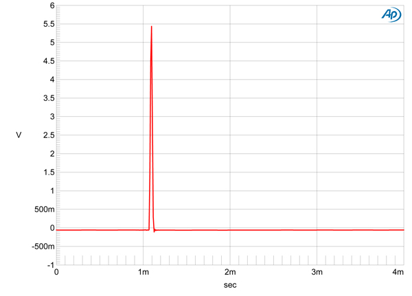
the statement about the Ares not being true 'NOS' does not compute for me. Your picture of the egyptian pyramid Vectrex style is not convincing. If anything it proves you made a mistake somewhere that you're unaware of. But its not simply showing oversampling. Or is is 1024 times oversampling? If it were say, 8x oversaming you would see stairs. No? And why I object: where is the preringing you always see with OS?

these are from the stereophile review of Terminator /Ares II and this is on par with what I know to expect from 'NOS' and the main reason I prefer Nos R2R, as you can see there is a real transient and *no* pre-ringing.
Denafripfig01.jpg


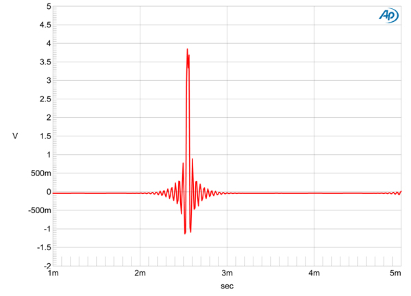
And this is the 'OS' mode where you can see the clear fingerprint of OS by the pre-ringing ripple *before* the transient.
Denafripfig02.jpg

Source: Stereophile https://www.stereophile.com/content/gramophone-dreams-40-denafrips-terminator-ares-ii-measurements

You can talk about frequencies all you like but what I want to see is a proper spike
(this could be my one-liner when it comes to dacs because there has always been almost exclusively attention to frequencies and 'linearity' and almost none to temporal behavior which is even more important to natural sound and soundstaging/hall)
 
May 10, 2021 at 8:53 PM Post #202 of 1,488
the statement about the Ares not being true 'NOS' does not compute for me. Your picture of the egyptian pyramid Vectrex style is not convincing. If anything it proves you made a mistake somewhere that you're unaware of. But its not simply showing oversampling. Or is is 1024 times oversampling? If it were say, 8x oversaming you would see stairs. No? And why I object: where is the preringing you always see with OS?
So the key thing here is that ringing is not inherent to oversampling. It's inherent to the sinc function which is the on-paper 'ideal' oversampling/interpolation method. (Though the real-world challenges make that claim quite debatable).
The vast majority of DACs oversample using sinc. But there's nothing mandating that you have to do so.

The oversampling filter can be designed in a manner which all but eliminates ringing at the expense of other factors like ultrasonic attenuation.
For example this is a very low tap count (sometimes called a "short" or "slow") sinc filter's impulse response:

1620692268644.png


And in fact you can do oversampling using alternative methods such as cubic interpolation, or polynomial interpolation which will have no ringing at all:

polynomial-1 impulse.png


And if you wanted to, you could also oversample using a 'Zero-order-hold' filter which would effectively replicate the behaviour of a NOS dac:

1620692653248.png


In fact there are some products which have this, the RME ADI-2 has a 'super slow' NOS emulation filter, so the 1khz sine output looks like this even though it's a delta sigma dac:

1620692754521.png


I've actually put recordings and images of the impulse response of all of the HQPlayer filters in a folder here if it's something you (or anyone reading) might find interesting:
https://drive.google.com/drive/folders/1WxYcmd-16NHLD5wMsss8MKmFj2vcvVK8?usp=sharing

There's also white noise recordings with images to show close-in and wideband ultrasonic attenuation behaviour.
I also added Square wave and 19khz+20khz sine tests for all of them though haven't gone through and put in screenshots of those so the recordings will need to be put into a program like adobe audition to look at them.


these are from the stereophile review of Terminator /Ares II and this is on par with what I know to expect from 'NOS' and the main reason I prefer Nos R2R, as you can see there is a real transient and *no* pre-ringing.
The problem here is that the time axis is too long and so we can't actually see what's going on.

If we use the same 1ms/div view as in the stereophile article then yep it certainly looks ok there
1620693020428.png

But then zooming in to a level where it's easier to view we can much more clearly see the behaviour of the IR:
1620693107497.png


We can tell that this is not NOS because a true NOS impulse will be either a square (DAC moves up to value of sample, holds, then moves directly down to value of next sample), or a slightly rounded square (result of the previous description put through an analog low-pass filter or other analog reconstruction).

So this sketch illustrates what actual NOS behaviour would do (I'm sure you know exactly how this all works of course but I figure it might benefit those who happen upon this thread later who may not be familiar):
1620693478508.png

- Sample 1 is received by the DAC, nothing happens and it holds at 0 until the next sample.
- Sample 2 is received by the DAC, it immediately moves up to the value of sample 2 and holds until the next sample
- Sample 3 is received by the DAC, it immediately moves down to the value of sample 3
- Sample 4 is received, same value as sample 3 so voltage stays where it is.

BUT, that isn't happening on the denafrips.
Instead, immediately after sample 1 arrives, it begins moving up toward sample 2. The only way this could happen is if additional samples had been interpolated in-between samples 1 and 2, ie: it was oversampling.
It is using a filter that introduces no ringing, but it is nonetheless still oversampling.

We can actually do another quick check to make sure that the dots illustrated above are indeed where the 44.1khz samples are:
1620694263693.png


Take the time between the bottom of the IR and the peak: 8.647631-8.647608=0.000023s
And then the gap between samples for 44.1khz audio: 1/44100=0.000023s
 
May 11, 2021 at 8:20 AM Post #203 of 1,488
This is fine, just a reminder that the first aggressive response came from you.

In fact, there is no reason to dispute a topic of compensation in a digital section, as you continuously confuse FPGA with DSP. Linear compensation in these DACs is made in FPGA, this is a fact. However it is done in a manner of a pure traditional logic alternation of individual bits based on a correction table stored in the device. It has nothing with DSP. In examples you brought in to the dispute nobody talks about DSP based compensation, not a Stereophile, neither Audio GD. They talk about linear compensation in FPGA, nothing more.

The following entire elaboration section about a subsample compensation is your complete immagination. Where, did you hear it. :)
There is an array of switches for driving individual bits of the ladder. In Denafrips these are shift registers, data is transfered from FPGA serially, then in one clock everything is transfered to the output. In Audio GD there are D-latches, all data is transfered in parallel. You can verify a frequency in NOS mode that it matches a current sample rate. It means, no subsample compensation.
This will be my last response as whilst I'm more than happy to have a discussion or debate about what is quite an interesting topic, your responses seem to be getting somewhat aggressive and I'm not interested in an argument.


You said "because if any compensation methods are used in the digital section, it doesn't affect a physical signal propagation across the ladder.".

Firstly, yes it could. Most R2R designs now have the ladders controlled in a parallel fashion which would allow the FPGA to flip bits as needed and a single clock cycle can be used to change the entire ladder. And there is no reason why this couldn't be done in a sub-sample fashion. Perhaps even correcting or changing the ladder state several times per sample.

Secondly neither denafrips nor holo's compensation methods affect signal propagation across the ladder.

On holo the signal is converted in typical fashion by the ladder, and then after, a small voltage value determined by the second ladder is summed to the main output to correct the result.
On denafrips the signal is converted in typical fashion by the ladders, and then after, they are summed to average out noise and linearity error.

Neither of these methods affect how the initial conversion on the ladder is done and whether the signal propagates through the ladder in "True" r2r fasion or not. It only affects what happens AFTER. And if there is concern about what happens after the ladder making things "True" r2r or not then we'd have to discuss everything all the way through to the output stage. Does the analog reconstruction/lowpass filter need to be done a specific way too?

Though whether either of them are doing further compensation using the FPGA or not we can't know for sure unless either of them disclosed it.
Audio GD DOES disclose this though and quite openly says they do use the FPGA to correct the ladders.
1620683994196.png

Denafrips is most likely doing DSP based correction as well as evidenced by the customised transfer function interfering with the linearity test done by John Atkinson in a fairly deterministic way. (And the fact that even in "NOS" mode their DACs are actually still oversampling just with fully linear interpolation. AND the fact that their DSP boards have been revised several times and users of the terminator for example can upgrade the DSP board itself to get a change/improvement to the DAC without even touching the ladder.)
1620683812797.png


You didn't, Audio GD did as shown above.
Also DSP just means digital signal processing. It can involve anything that would alter the signal passed to the converter. Including on-the-fly ladder correction handled by the FPGA.


I'm aware, hence I said they are using analog domain compensation. The use of multiple converters and summing the result is analog domain compensation.
In a perfect world each time you double the number of converters (be it R2R ladders or 1-bit converters) you should get 6dB better performance. Though of course in the real world other factors will be limiting so we can't endlessly stack converters. I did see a TDA1541 DIY project with about 20 stacked chips once though which looked both crazy and interesting.
 
May 11, 2021 at 8:47 AM Post #204 of 1,488
We can actually do another quick check to make sure that the dots illustrated above are indeed where the 44.1khz samples are:
1620694263693.png


Take the time between the bottom of the IR and the peak: 8.647631-8.647608=0.000023s
And then the gap between samples for 44.1khz audio: 1/44100=0.000023s
Right, I asked to show sampling boundaries of this mysterious Egiptian pyramid initially, it was no response. Now it is clear what is happening. There is no delay, no DSP processing, no internal oversampling.

In the sample (n) - point #1 - output is driven from bottom to the top. What you see on the screen between #1 and #2 is an integration on the capacitor according to the RC constant. R is an internal ladder output impedance (a few kOhm) , C is a capacitor value for the reconstruction filter. In the sample (n+1) - point #2 - output is slowly changing back to the bottom.

Everything is as it should be in the best world on the passive output. Remember that on the passive output (which is in the Ares) I/V conversion take place immediately. You will not see discrete values in such circuit, only averaged.
 
Last edited:
May 11, 2021 at 12:04 PM Post #205 of 1,488
Right, I asked to show sampling boundaries of this mysterious Egiptian pyramide initially, it was no response. Now it is clear what is happening. There is no delay, no DSP processing, no internal oversampling.

In the sample (n) - point #1 - output is driven from bottom to the top. What you see on the screen between #1 and #2 is an integration on the capacitor according to the RC constant. R is an internal ladder output impedance (a few kOhm) , C is a capacitor value for the reconstruction filter. In the sample (n+1) - point #2 - output is slowly changing back to the bottom.

Everything is as it should be in the best world on the passive output. Remember that on the passive output (which is in the Ares) I/V conversion take place immediately. You will not see discrete values in such circuit, only averaged.
This is fine, just a reminder that the first aggressive response came from you.

In fact, there is no reason to dispute a topic of compensation in a digital section, as you continuously confuse FPGA with DSP. Linear compensation in these DACs is made in FPGA, this is a fact. However it is done in a manner of a pure traditional logic alternation of individual bits based on a correction table stored in the device. It has nothing with DSP. In examples you brought in to the dispute nobody talks about DSP based compensation, not a Stereophile, neither Audio GD. They talk about linear compensation in FPGA, nothing more.

The following entire elaboration section about a subsample compensation is your complete immagination. Where, did you hear it. :)
There is an array of switches for driving individual bits of the ladder. In Denafrips these are shift registers, data is transfered from FPGA serially, then in one clock everything is transfered to the output. In Audio GD there are D-latches, all data is transfered in parallel. You can verify a frequency in NOS mode that it matches a current sample rate. It means, no subsample compensation.

Ok...so instead of whipping out the e-peens and trying to play stump-the-chump, would you mind telling me what any of this actually means for analog vs digital presentation, overall sound quality, or sound differences between the DACs mentioned in this review? I'm genuinely interested. I tested the May against an RME ADI-2 with digital files from Qobuz, then compared them both against an old record player + receiver and the differences were stark. The May sounded much more analog and smooth to my ear compared to the RME and I've often wondered why this is. What mechanisms inside the May lend themselves to more of an analog sound presentation compared to the RME or the Chord Dave I tried at the dealers? All of this is quite fascinating to me.

Furthermore, I think its amazing how far digital music has come. It still doesn't have quite the same impact or separation as records do in my humble opinion, but it's definitely getting there.
 
Last edited:
May 11, 2021 at 12:17 PM Post #206 of 1,488
I think someone is missing the point. I made a distinction between pre and post-ringing.

There is always ringing visible on the output of any dac I've seen in graph, no matter how you massage the data, scale of axis etc. If you look at the graphs I posted there is minor post-ringing on the Denafrips NOS. When oversampling there is a lot more ringing but its not just after the peak but it introduces ringing ahead of the actual transient. This is the same behaviour I've seen on any sigma delta dac. I've never seen real live graphs as clean stepless even slopes as in the graphs above. This tells me its all very theoretical but not what is actually coming out at the end of the signal path.

(Unless I'm mistaken) it's very easy to spot real NOS on transient respons.
 
May 11, 2021 at 1:27 PM Post #207 of 1,488
Ok...so instead of whipping out the e-peens and trying to play stump-the-chump, would you mind telling me what any of this actually means for analog vs digital presentation, overall sound quality, or sound differences between the DACs mentioned in this review? I'm genuinely interested.
Genuinely, you are not. Otherwise you would prepare a question different way.

A reviewer made a claim that Ares II had no real NOS mode and some other fantastic stories were created solely in purpose avoiding admission to a mistake. Now it is clear, that it was a general lack of knowledge of electronics and following misinterpretation of the test result. It is all we need to know about Ares II. On the other side there is an unsolved issue of a mystery osciloscope output from a Holo Audio DAC in this post.
 
Last edited:
May 11, 2021 at 1:43 PM Post #208 of 1,488
Genuinely, you are not. Otherwise you would prepare a question different way.

A reviewer made a claim that Ares II had no real NOS mode and some other fantastic stories were created solely in purpose avoiding admission to a mistake. Now it is clear, that it was a general lack of knowledge of electronics, it is all we need to know about Ares II. On the other side there is an unsolved issue of a mystery osciloscope output from a Holo Audio DAC in this post.

I am indeed interested, in layman's terms, as to how analog-ish sounds come from digital signals...specifically as it relates to the May, RME, and the Dave. But it seems you (and others in this thread) would rather have incredibly pedantic arguments while you try desperately to prove the other guy is wrong/stupid. Even in your response to me, you couldn't help yourself. You had to re-state your case as to why GoldenOne is wrong and uninformed, even though I purposefully tried to steer the conversation in another direction. You clearly have an axe to grind, so I'm just going to leave you guys to enjoy your pointless game of stump the chump. I'll go Google stuff...
 
Last edited:
May 11, 2021 at 1:55 PM Post #209 of 1,488
I am indeed interested, in layman's terms, as to how analog-ish sounds come from digital signals...but it seems you (and others in this thread) would rather have incredibly pedantic arguments while you try desperately to prove the other guy is wrong/stupid. Even in your response to me, you couldn't help yourself. You had to re-state your case as to why GoldenOne is wrong and and uninformed, even though I purposefully tried to steer the conversation in another direction. You clearly have an axe to grind, so I'm just going to leave you guys to enjoy your pointless game of stump the chump. I'll go Google stuff...
I am not a person giving a proof who my respondent is, I do not make such comments, you did. It would be much easier to admit to a simple mistake instead of preparing pseudo-scientifical theories with errors in almost every sentence.
 
Last edited:
May 11, 2021 at 2:08 PM Post #210 of 1,488
I am not a person who is proving who my respondent is, I do not make such comments, you did. It would be much easier to admit to a simple mistake instead of preparing pseudo-scientifical theories with full of errors in almost every sentence.
LOL. Thanks for proving my point. Again. Clearly, this review (or Golden's subsequent responses) really got under your skin. Calling someone out when you think they are spouting BS is hard to pass up - I get it. I also get why you are so passionately arguing about it. I just assumed everyone's time would be better spent discussing information that might help people educate themselves and make informed decisions.

Regardless, I'm just going to stay out of it and let you guys finish the e-peen sword fight. I'll go Google stuff to find out why the May seems to sound more analog/smooth than the RME or Dave does.
 
Last edited:

Users who are viewing this thread

Back
Top