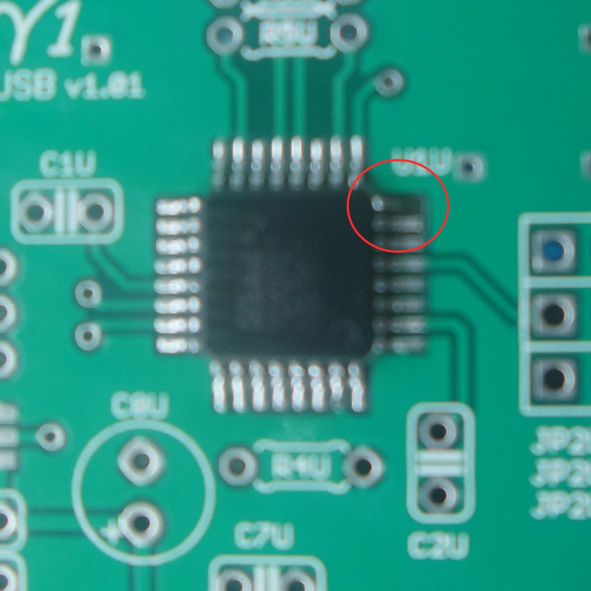
Check for cold joints on U3U, in particular pin 2 (the middle one on the side with 3). It should be connected to ground. You can use the ground strips along the edges of the board for your DMM.
Originally Posted by Bismar /img/forum/go_quote.gif I reflowed U2U and U3U still ~4.5 volts on the 3.3v test point.
Is it possible i may have damaged one of the SMD's? And if so, how do i test if they are dead?
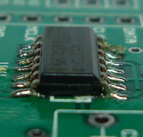
Well, before you gebugging anything else, the supply voltage has to be right first. That leaves only the voltage regulator chips themselves. Did you use the wrong chip for U3U? What does its markings say?
Ok, so it's the correct chip. Aside from bad solder joints there is not much else that could cause the voltage to be incorrect, unless the regulator itself is blown (as an internal short).
I don't have spares of either of those, only have a spare PCM2707 but that's hard to remove and i wouldn't want to unless you guys are really sure.
I already tried reflowing the joints, so i don't think its a bad solder joint. Is there anything else i can test ? Maybe some other component thats linked to either of those chips under power?
Nothing will cause the voltage regulator to output more voltage than what it's supposed to output, unless its ground reference pin is not making contact to circuit ground, or there is a short circuit from its input to output (which could be an internal short due to a blown regulator, or a solder bridge somewhere, or a PCB defect). You said that you/ve reflowed the regulator's joints, so you've probably eliminated the first possibility. That leaves the others. Have you measured the resistance between pins 1 and 5 of the voltage regulator chip?
Originally Posted by amb /img/forum/go_quote.gif Nothing will cause the voltage regulator to output more voltage than what it's supposed to output, unless its ground reference pin is not making contact to circuit ground, or there is a short circuit from its input to output (which could be an internal short due to a blown regulator, or a solder bridge somewhere, or a PCB defect). You said that you/ve reflowed the regulator's joints, so you've probably eliminated the first possibility. That leaves the others. Have you measured the resistance between pins 1 and 5 of the voltage regulator chip?
That's correct, without U3U there shouldn't be any voltage at the 3.3V test point. The 5V test points should still be about 5V when it's plugged into the USB port. Obviously, without a 3.3V to supply the chips the computer won't detect anything.
If you still get more than a couple volts at the 3.3V test point without U3D, then there is a short somewhere on the board.
This site uses cookies to help personalise content, tailor your experience and to keep you logged in if you register.
By continuing to use this site, you are consenting to our use of cookies.