Topaz Low-Capacitance Isolation Transformers - for Affordably Clean Power
Jul 9, 2018 at 10:34 AM Post #181 of 562
Hi Mike:
I think the reason John adviced against use of DC-offset blocking networks was concern for safety—as failure of such can result in a fire. Given that these are used on the primary side, I don’t think he was advising against them for performance reasons.

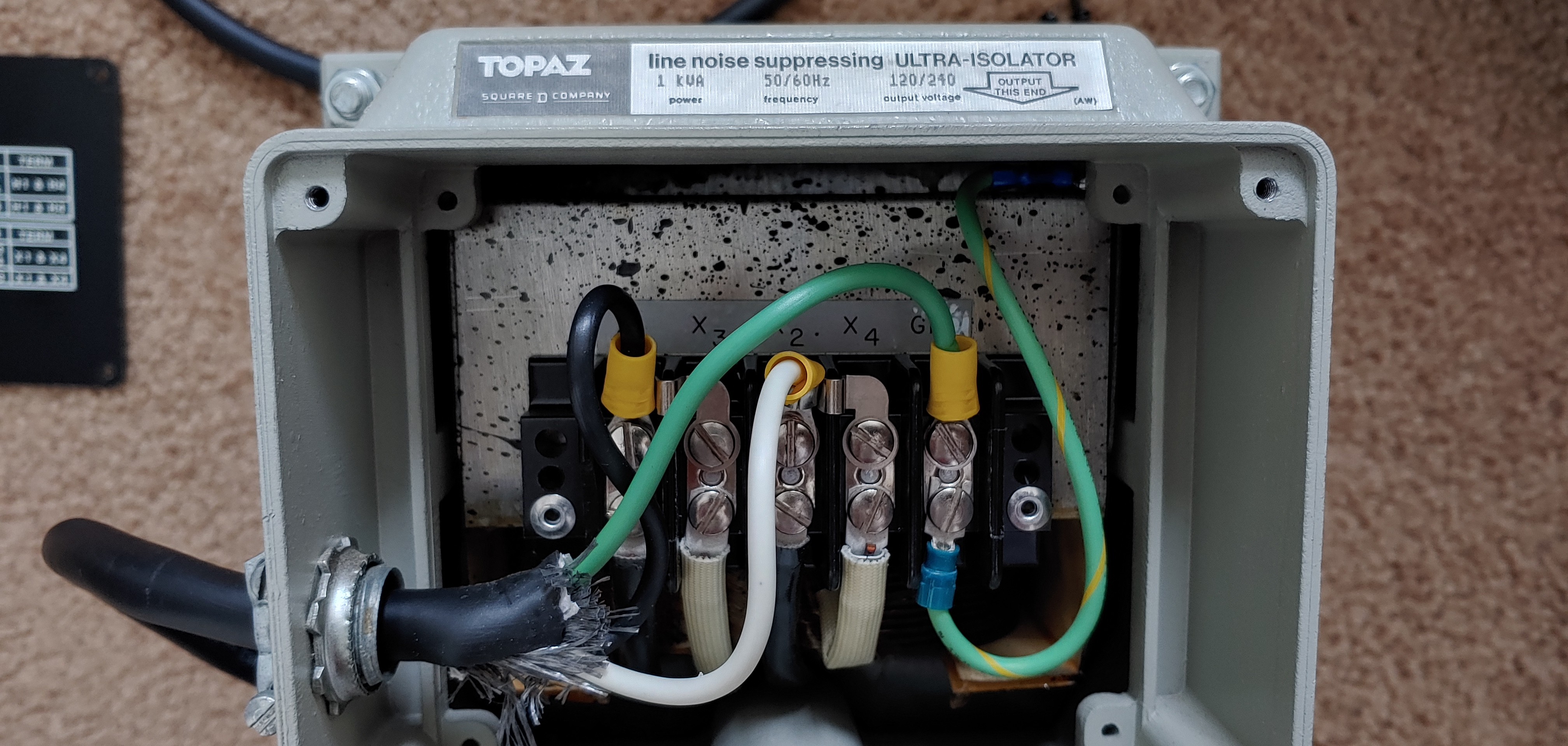
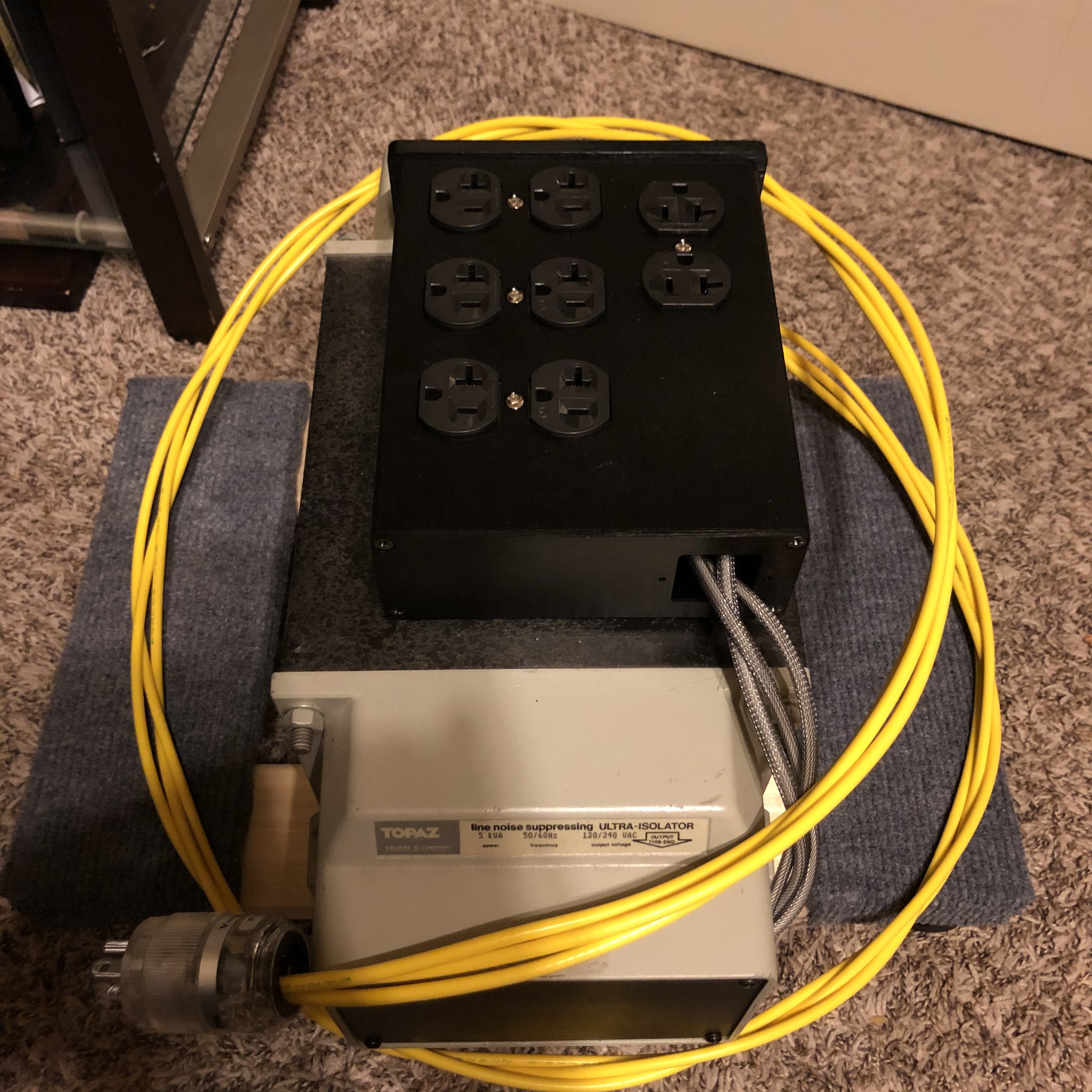
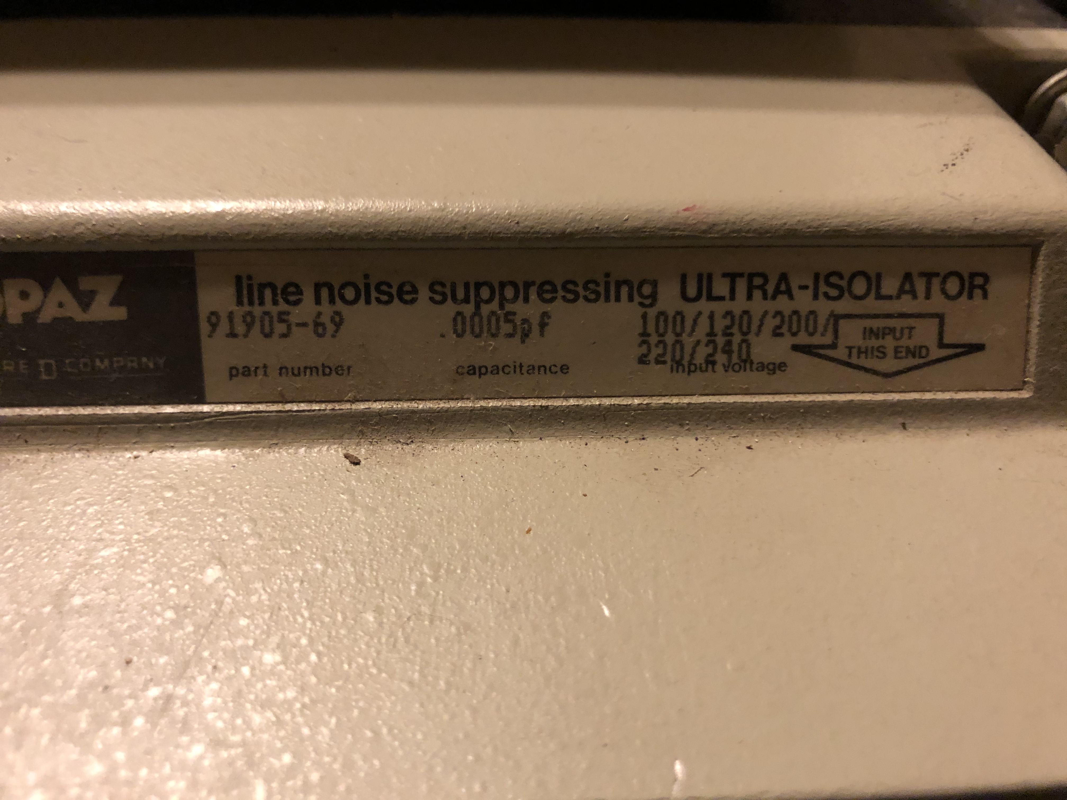
Of course on the secondary side it is important to use outlets/power strips that have zero filter elements at all. The whole concept being to reduce the impedance between the grounds of all attached equipment (reducing the interaction of the inevitable leakage loops which form between all components with AC-connected power supplies). And the point of the isolation transformer is simply that it is a VERY effective surge suppressor and line noise filter.

BTW, here in the USA DC offset in our AC lines is rather rare. Occurs much more in Europe. Even there, blocking of the offset is not a sure-fire cure for transformer lamination hum. Such is a bit inevitable with big trannys—and it is often worse in 50Hz countries.

Hey Alex! Thanks very much for the clarification!

I couldn't remember the details of John's advice regarding DC filters (nor even how to spell his first name!) LOL

Like watching a movie you haven't seen in years, everything you've written came back to me as I read it. Sheesh!

And for those who don't know Superdad, he and John Swenson are the guys behind UpTone Audio, who produce all the products seen here, which I have no reluctance to plug, as I'm a huge fan of their products and their knowledge of all things related to noise reduction:

https://uptoneaudio.com/

https://www.computeraudiophile.com/forums/forum/25-uptone-audio-sponsored/

In other words, whenever you see a post by Superdad or John Swenson, here or at ComputerAudiophile, pay attention! :)

Mike
 
Jul 9, 2018 at 9:27 PM Post #182 of 562
20180709_182409.jpg download.jpeg 088700955806lg.jpg 050169005002lg.jpg Free-shipping-one-pieces-audio-Rhodium-US-AC-Power-Receptacle-distributor-Wall-outlet-Socket.jpg 20180613_144921.jpg Copying this over from the ca thread would just like to make sure I'm gettin this setup correctly.

"
So per one and a half and john swensons advice I added a 250v 2a ceramic time delay fuse to the transformer. The prewired 250va model says to use a 6a fuse, the 125va a 3a fuse. I have the transformer wired 120 in 120 out and can't be putting more then a 1a load on it(specs say 50w dac 30w headphone amp).


Id just like to confirm grounding of the electrics boxes though.


I have the input like this(attached pictures ignore the red wires on the terminals those r gone now
Metal box
Pvc terminal adapter and brushing
Metal cover plate with fused iec inlet

Is this ok? In this situation the metal box isn't grounded. On the output I'd use a metal electrical box and the standard ac outlet grounds to the box just by attaching it.

Thanks so much for the help and to everyone whos contributed to this thread the transformer makes a massive difference
 
Last edited:
Jul 10, 2018 at 6:14 AM Post #183 of 562
Copying this over from the ca thread would just like to make sure I'm gettin this setup correctly.

"
So per one and a half and john swensons advice I added a 250v 2a ceramic time delay fuse to the transformer. The prewired 250va model says to use a 6a fuse, the 125va a 3a fuse. I have the transformer wired 120 in 120 out and can't be putting more then a 1a load on it(specs say 50w dac 30w headphone amp).


Id just like to confirm grounding of the electrics boxes though.


I have the input like this(attached pictures ignore the red wires on the terminals those r gone now
Metal box
Pvc terminal adapter and brushing
Metal cover plate with fused iec inlet

Is this ok? In this situation the metal box isn't grounded. On the output I'd use a metal electrical box and the standard ac outlet grounds to the box just by attaching it.

Thanks so much for the help and to everyone whos contributed to this thread the transformer makes a massive difference
No picture attached.
 
Jul 10, 2018 at 12:51 PM Post #184 of 562
Jul 11, 2018 at 11:56 AM Post #185 of 562
Thx fixed it
I would think it would be ok. I only have a -32 at the moment because my -31 is being shipped but in -32 the grounding goes through the transformer case and probable does in the -31. The metal box on the input side shouldn’t need to be grounded as the rest of the transformer is.
 
Jul 11, 2018 at 12:04 PM Post #186 of 562
Here’s a question for the group. On the 91002-32 there is a 7uF capacitor connecting the live to neutral side of the built in recpeptacle. I surmise this is for so sort of filtering. Does anyone else concur? It is the black wire in the photo.

6D532AD2-EBB0-426D-97E1-1FE37C0139AB.jpeg
54D023C6-2BAD-43DB-A40B-84ABD68F142A.jpeg
997A7F03-EF62-45AF-BC5E-816A7DCAA544.jpeg


This isn’t present in the -31 so my plan is to omit it when I build 91002-32 into an aluminum enclosure with 3 outlets just as with my -31 enclosure build.
 
Jul 11, 2018 at 1:17 PM Post #187 of 562
Here’s a question for the group. On the 91002-32 there is a 7uF capacitor connecting the live to neutral side of the built in recpeptacle. I surmise this is for so sort of filtering. Does anyone else concur? It is the black wire in the photo.


This isn’t present in the -31 so my plan is to omit it when I build 91002-32 into an aluminum enclosure with 3 outlets just as with my -31 enclosure build.

The topaz pdf says its for additional traverse noise attenuation.
 

Attachments

  • tp-91092-31_N.pdf
    1.2 MB · Views: 0
Jul 11, 2018 at 1:22 PM Post #188 of 562
Jul 11, 2018 at 1:29 PM Post #189 of 562

Attachments

  • tp-91092-31_N.pdf
    1.2 MB · Views: 0
Aug 22, 2018 at 2:57 AM Post #190 of 562
So I’m disassembling my 91002-32 so it can be rewired to have 3 duplex outlets in and an aluminum case and I had a question about how it came wired. On the receptacle that came with the transformer neutral was tied into ground. Any idea why this mat have been done?

52EB3061-F796-470C-9A89-C76D8A4A4602.jpeg 34D6AE16-7B9A-4FCB-8939-9E2D9B393479.jpeg

Here are a couple more pics people may find interesting:

CB840160-3B06-48F1-A037-9D5D7CD21D81.jpeg 3E59F2E3-9350-4A2E-BA79-7C7D651F5235.jpeg E8F84AAA-B1BF-4C61-AB46-6CA77386E0F3.jpeg76CD96A8-10A1-4864-99D9-5424EF07811E.jpeg
 
Last edited:
Aug 22, 2018 at 7:55 AM Post #191 of 562
Hey oneguy!

That's literally what defines these Topaz isolation transformers as having "grounded-neutral secondaries" as opposed to transformers like the B&K Precision, that have "floating-neutral secondaries. Both types provide common-mode noise rejection, with attenuation in the higher frequencies being inversely proportional to the inter-winding capacitance. The lower the capacitance between the coils, the higher the frequencies at which we can enjoy CM noise reduction.

The secondary's neutral is grounded in the interest of safety. In the States, the NEC requires Neutral to be bonded to Ground at the mains entrance so that a ground fault will trip the circuit breaker.

A transformer with an ungrounded secondary is actually beneficial for energizing equipment on a workbench, where the chassis is open and the user is inserting probes onto energized components. You can find YT videos where guys who repair electronic equipment explain how to modify a grounded-neutral secondary to turn it into a floating-neutral secondary. These videos also include diagrams showing how doing so reduces shock hazard when working with an energized open chassis.

For our purposes, it's safest to use a grounded-neutral secondary. See the blue text in this graphic:

image.jpeg
 
Last edited:
Aug 22, 2018 at 8:39 AM Post #192 of 562
Hey oneguy!

Thanks for the refresher. I read that graphic sometime ago and forgot that it mentioned grounded-neutral secondaries.
 
Aug 22, 2018 at 11:27 AM Post #193 of 562
My 91092-12 came new sealed in the original packaging and doesn't look like that.

20180803_123041.jpg
 
Aug 22, 2018 at 1:14 PM Post #194 of 562
My 91092-12 came new sealed in the original packaging and doesn't look like that.

Yours is a -12 not a -32 so thats probably why (different model series). The -31 and -32 series are the ones with the lowest capacitance.
 
Aug 22, 2018 at 2:08 PM Post #195 of 562
Yours also has the capacitor, that could be why. I have a -31 also and I've never seen any wiring scheme that said to jumper the common and ground.
 

Users who are viewing this thread

Back
Top