


Merlin-PT
500+ Head-Fier
- Joined
- Jan 21, 2005
- Posts
- 600
- Likes
- 691
@Ivan TT
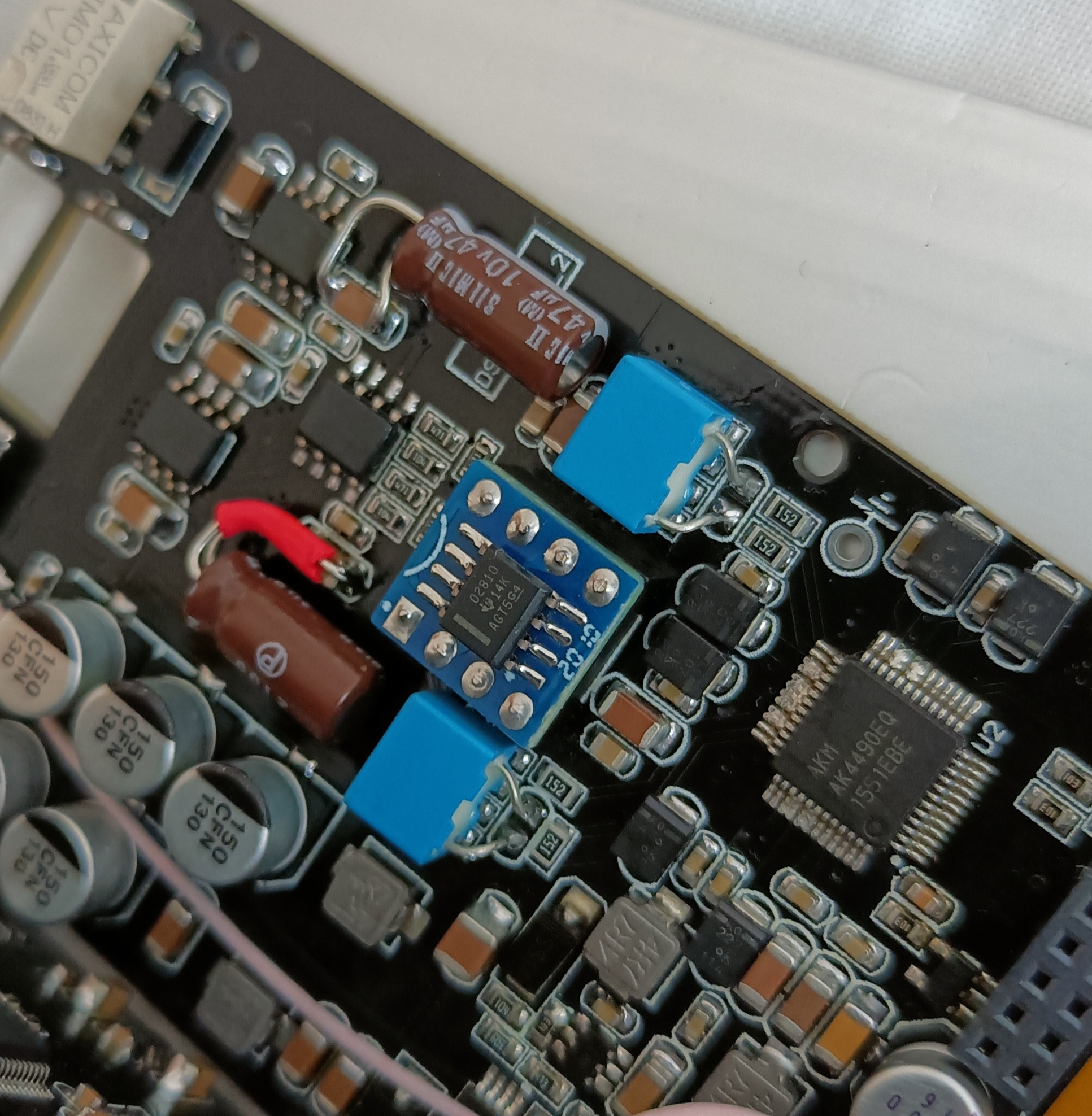
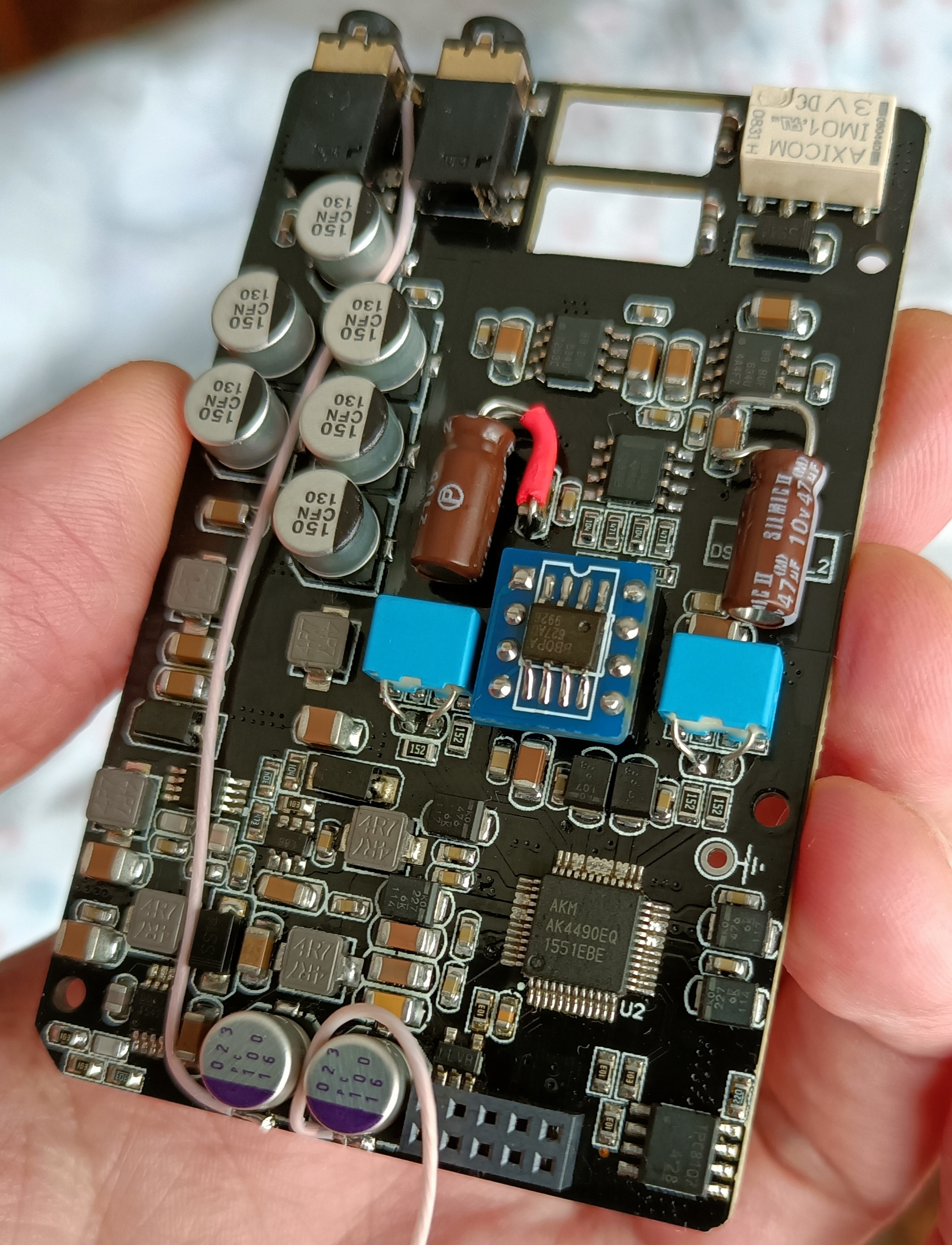
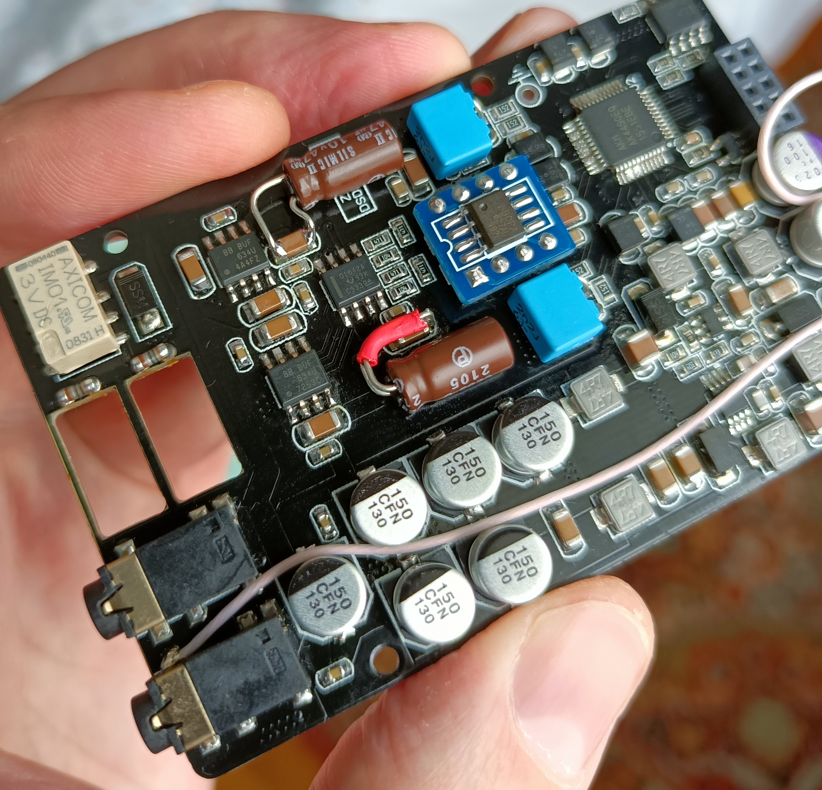
Do you mind sharing the capacitors you use in the DAC VREF?
It's difficult to find high capacity and low size.
I found this but the drawback is they are rated for 40C, 40C seams too low...
https://www.arrow.com/en/products/t490b337m006ate800/kemet-corporation
Do you mind sharing the capacitors you use in the DAC VREF?
It's difficult to find high capacity and low size.
I found this but the drawback is they are rated for 40C, 40C seams too low...
https://www.arrow.com/en/products/t490b337m006ate800/kemet-corporation
Last edited:

")


