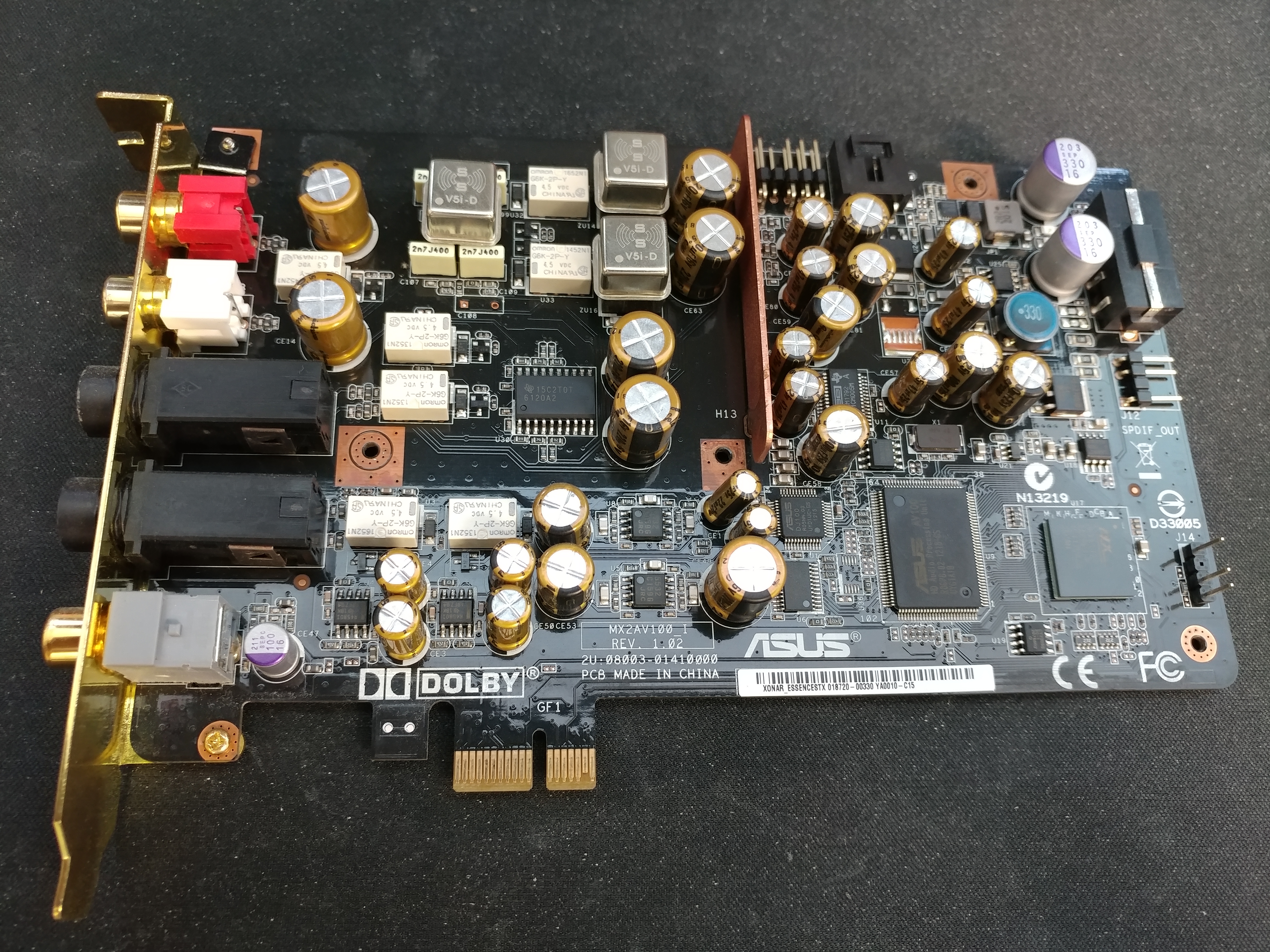
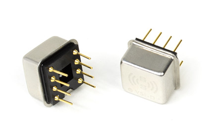
Well, I don’t know if it was the prospect of a long weekend or the turkey, but I did my “not-so-great” idea and attempted to desolder the DIP8 holders from my STX II and re-solder them to the opposite side of the card. This then allows room for attaching Burson’s SS v5 op amps; given the total lack of room below the sound card with my current dual graphics card configuration.
In order to make this work, you have to take into account that the pin-outs on the other side of the sound card will be reversed (pin 1 is where pin 8 should be, pin 2 is where 7 should be, etc.). To correct for this I ended up buying several blank bread boards from Radio Shack (yes, some are still open) and tried wrapping my head around exactly how to do the switcheroo.
Of course the first step is removing the current DIP8 sockets from the sound card and re-soldering them to the other side of the card. Desoldering the bracket pins pretty much destroyed them, so thankfully Radio Shack had ready replacements available. This proved to be the most difficult part of the project, and I was a more than a little worried that I’d created shorts during the re-soldering of the brackets.

Due to the miniscule size of the DIP8 bracket pins and my lack of soldering skills I ended up using 22 gauge solid core copper wire with standard insulation. I created 8 legs for each op amp module (obviously); each leg is 5/8” long with 1/8” of insulation stripped away. This stripped area is just pressure fitted into the Radio Shack DIP8 socket – no solder. The leg then bends to the opposite side of the socket and then bends upward to meet the pin of the DIP8 bracket that came with the SS v5’s. After having bent each leg into this shape (3 x 8 = 24 legs!) I then carefully pressed and removed a sewing pin into the upward portion of each leg to create some room for the bottom pin of the SS v5’s bracket. Again, this connection was simply pressure fitted as well – no solder. I realize this isn’t “best practice electronics” but the solder was just rolling off the joints and causing the insulation to shrink, possibly causing a short due to the close proximity of the legs.


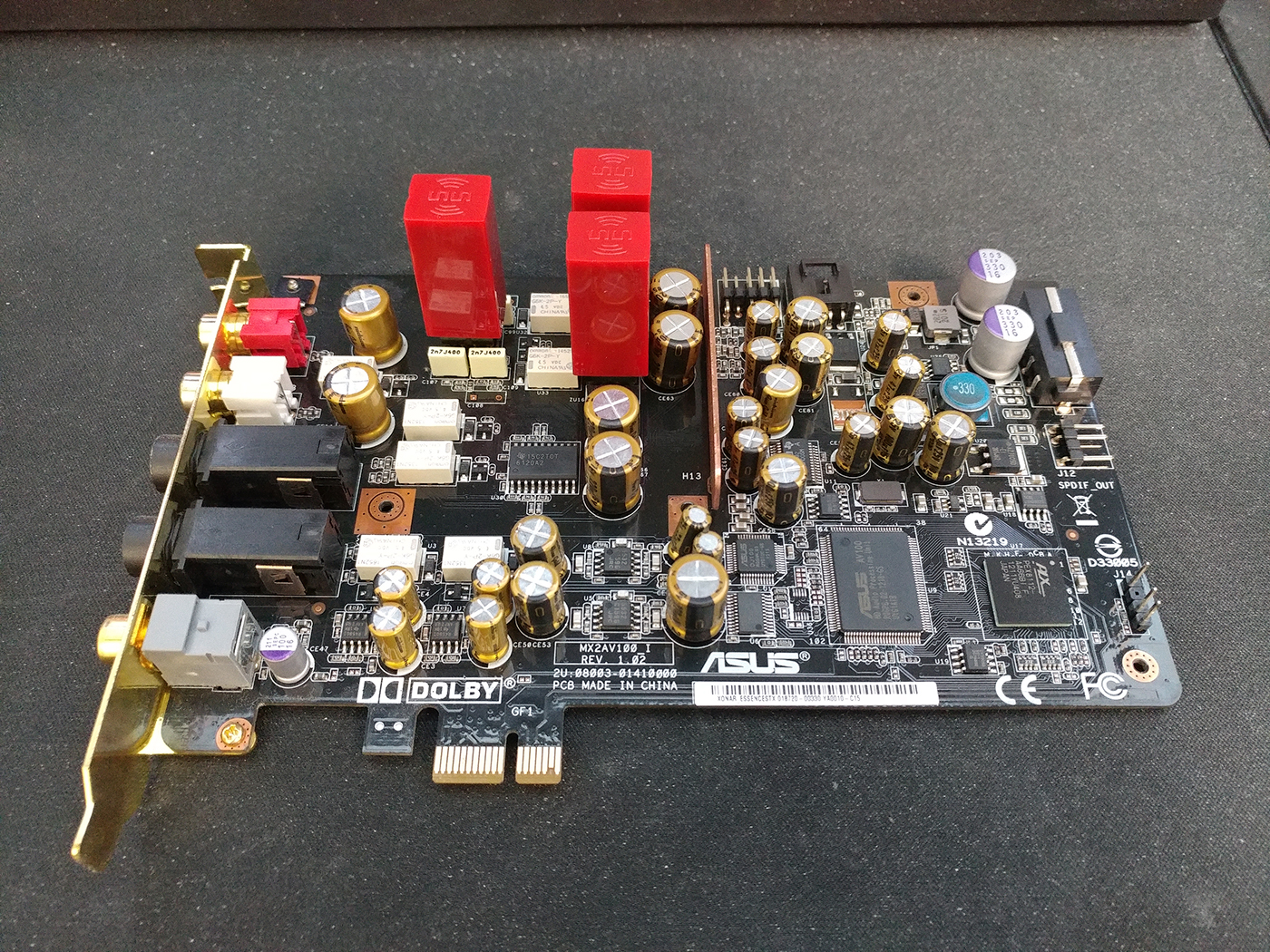
I eventually got each leg attached to the SS v5 socket. A little tidying is done to get the legs roughly in a row and then it’s time to plug one side of legs into the DIP8 socket on the board. Needless to say, needle-nose pliers are a necessity. Once one side is in, the challenge is getting the other side in to their individual sockets without disrupting the original side. With some patience and a few breaks I was able to get all three brackets ready before dinner.

I then popped in the secondary op amps that came with the card and shoe-horned the card back into its position in my case (did I mention I have a water cooling loop w/ two graphics cards?). I basically made sure everything is connected and in its rightful place, fired up the system, and plugged in the headphones to the STX II. I must stress again how poorly the removal of the original brackets went (had to use a sewing needle heated by the soldering iron and press down with a lot of force to clear the sound card’s contact holes), and attaching the replacement DIP8 brackets to the card wasn’t much smoother either. I wasn’t about to power everything on and have the SS v5’s go up in smoke – the loss of the replacement op amps I could stand. Yes, I realize that would probably mean the card is forever ruined too, but why lose $$$$ when you can do some risk mitigation and merely lose $$? To my relief everything sounds alright. Checked out the left and right channel jacks as well – those sound good too. Quite a relief. Downed some very-berry pie (sorry, no pumpkin this year) to celebrate.

Last step was popping out the replacement op amps and plugging in the SS v5’s. Thankfully the replacement amps came out much easier than the original ones that come with the card. The SS v5’s in their place, I close everything up and start the 100 hours burn-in.
Anyone who knows anything about electronics will tell you the way I attached the wire “legs” to the top DIP8 socket is far from ideal. Solder has been around for a long while and is used for a reason: longevity of the electrical connection, as well as providing
some structural support. That being said these circuits aren’t going for a bumpy ride in a car, nor are they shouldering mission critical communications on the lunar lander module, so I guess I get a passing grade on this one. Not much better though. Maybe if I had more time to think this through and the #@$%@# solder would actually adhere (even used some flux – to no avail) I’d have something that wouldn’t make an electrician smack his forehead in disgust.
Sorry for this tome of a post, but I’m pretty thrilled at what I’ve been able to pull off. I guess I just wanted show that it can be done. And can probably be done better by anyone other than me! Enjoy your long weekend.


")
