j4cbo
100+ Head-Fier
- Joined
- May 13, 2006
- Posts
- 118
- Likes
- 0
I've been working on my own amplifier design for a while now, and have finally come up with something that seems to be working well. My design goals were straightforward enough:
- Make it fully balanced. 2 channels will work well with good enough grounding, 3 channels improves things, 4 channels is a brute-force solution to deal with return currents; but a proper cross-coupled differential amplifier is the ideal topology. Unfortunately, the only existing DIY design for a non-tube-based fully differential amp is the Beta24, which conflicts with my other goals…
- Make it small and relatively low-power. This doesn't need to be battery-powered, but I don't want to have to deal with the massive heatsinking and casework of a Dynahi, Beta22, etc. A good amp should be able to fit in a mid-sized Hammond case without too much trouble.
- Make it integrated. An amplifier alone isn't good enough; power supply, attenuator choice, and I/O wiring are all important parts of the project. A σ22 would be nearly as large as I want the entire amplifier to be.
I wound up deciding to go for something that I don't think has ever been implemented before: a fully-balanced opamp coupled with two discrete MOSFET-based Class A output stages per channel. Significant portions of the amplifier circuit are based heavily on (or perhaps "lifted directly from
") AMB and Morsel's brilliant M³ design, since it is at the top of the heap of amplifiers with a hybrid opamp-FET design. I've made a few other tweaks along the way.
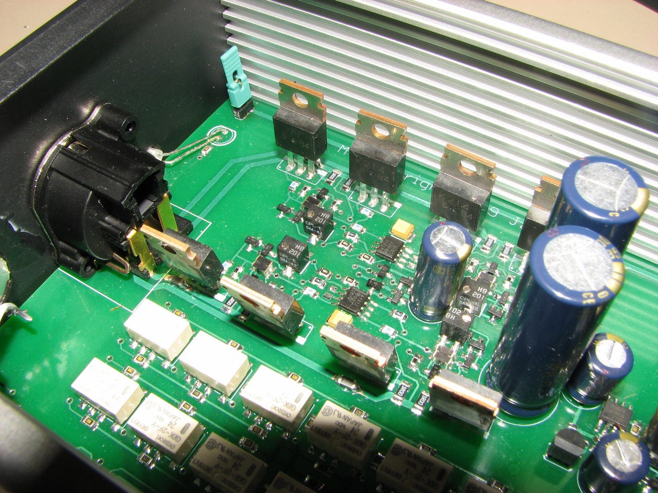
The output stages are within the cross-coupled feedback loop of the amplifier itself. I've used the output circuit from M³, with minimal changes. M4 uses lateral MOSFETs rather than vertical MOSFETs. The latter are cheap and robust, but designed for switching power supplies rather than operating in linear mode. Although one can build a great-sounding amplifier from vertical FETs, they require inordinately high bias currents to achieve good linearity. Although lateral FETs are significantly more expensive, they are inherently superior for audio purposes. The Vbe multiplier part selection had to be changed, since my FETs have somewhat different parameters than those originally specified, but other than that there is little difference.
M³ can use a simple TLE2426 rail splitter, because the varying return current from the headphones is sourced from or sunk to the power rails through a third amplifier stage. A precise, well-decoupled reference is still needed because the input signal is referenced to ground. In M4, the input signal return current passes through the feedback loop to the complementary input line, and so there is no ground current at all. In fact, M4 essentially has no ground reference. A network of 1M ohm resistors ensure that the floating power supply remains centered relative to the common mode voltage of the input, but that's all.
I didn't skimp on the power supply. M4 uses a Jung Super Regulator, the state of the art in power regulator circuits. The board takes a 24VAC wall-wart input, rectifies and filters it, and supplies the Super Regulator. Tangent's YJPS, a similar circuit, has been measured at 7 μV of output noise. I tried connecting my prototype to a 5-1/2 digit HP multimeter, which showed 2 μV AC; that's interesting, because the meter shows 4 μV with inputs shorted. In any case, it seems strangely appropriate to drive a combination opamp-discrete amplifier with a combination opamp-discrete regulator. As with M³, the opamp rails themselves are further isolated by a capacitance multiplier.
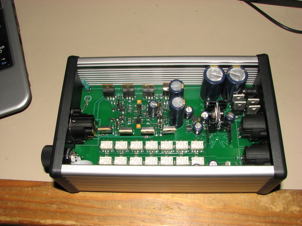
In addition to the amplifier and power supply, M4 also includes a 128-step relay based balanced logarithmic attenuator. Each stage is either a pass-through or a resistor divider which attenuates by 0.5dB, 1dB, 2dB, … 32dB. Since this is an integrated board, the attenuator can be designed with the assumption that it will always be driving the 10k differential load of the feedback loops; similarly, its input impedance is a constant 10k ohms as well.
A dedicated ATtiny24 microcontroller controls a pair of TI TPIC6C595 buffers driving Omron G6K surface mount relays. The microcontroller reads an analog value from a single-channel pot, and performs various conditioning before updating the relays: it adds hysteresis, limits the rate at which relays are switched to prevent excessive clatter when turning the knob quickly, and staggers the switching of multiple relays so noise doesn't get coupled into the circuit. The ATtiny24 is from the same architecture as used in the Arduino, but much smaller and cheaper. Rather than feeding the microcontroller and relays from the same clean power supply as the amplifier itself, they have their own 7824 and 7805 fed from the unregulated input voltage.
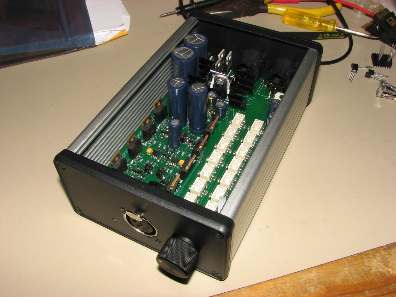
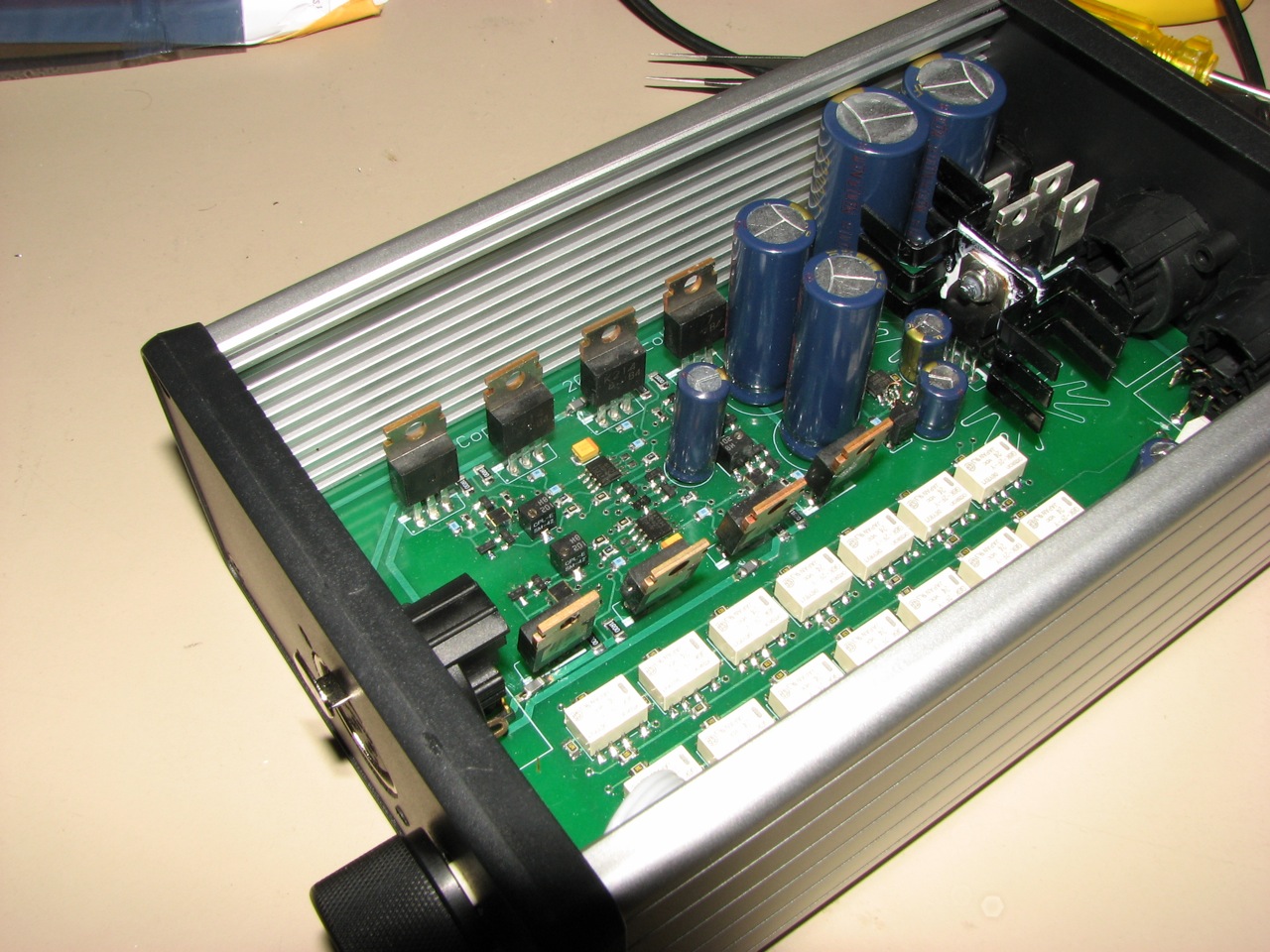
The whole thing is a single board. On the back, there are two board-mounted 3 pin XLRs and a power jack on. The front has a 4-pin XLR, power LED, and provisions for a panel-mount pot and switch. It slides into a Hammond 1455N1602 case, 2.1" by 3.8" by 6.3".
At this point, I've ordered boards, assembled a prototype, and got it up and running. After dealing with a few board layout and oscillation issues (I initially forgot to include ferrite beads in series with the outputs), it's generally good shape. The output stage is biased at 45mA, for a total draw of around 250mA. At this level of dissipation the TO-220s are quite hot to the touch, but comfortably within their specified operating area. The front and panels were recklessly hacked up with a Dremel, and will be replaced with something from FPE at some point. I'm working on drilling a whole bunch of holes in the top for ventilation. The only other current issue is a brief bit of static on power-up and -down, which I'd like to get rid of.
All in all, I'm pretty damn happy with the thing. Total parts cost will be around $300-$350, I think, depending on whether there's a group buy. I had the 2SJ76/2SK213 output transistors already from another project, and got everything else I needed on Mouser.
Without further ado, pictures!
- Make it fully balanced. 2 channels will work well with good enough grounding, 3 channels improves things, 4 channels is a brute-force solution to deal with return currents; but a proper cross-coupled differential amplifier is the ideal topology. Unfortunately, the only existing DIY design for a non-tube-based fully differential amp is the Beta24, which conflicts with my other goals…
- Make it small and relatively low-power. This doesn't need to be battery-powered, but I don't want to have to deal with the massive heatsinking and casework of a Dynahi, Beta22, etc. A good amp should be able to fit in a mid-sized Hammond case without too much trouble.
- Make it integrated. An amplifier alone isn't good enough; power supply, attenuator choice, and I/O wiring are all important parts of the project. A σ22 would be nearly as large as I want the entire amplifier to be.
I wound up deciding to go for something that I don't think has ever been implemented before: a fully-balanced opamp coupled with two discrete MOSFET-based Class A output stages per channel. Significant portions of the amplifier circuit are based heavily on (or perhaps "lifted directly from
") AMB and Morsel's brilliant M³ design, since it is at the top of the heap of amplifiers with a hybrid opamp-FET design. I've made a few other tweaks along the way.
The output stages are within the cross-coupled feedback loop of the amplifier itself. I've used the output circuit from M³, with minimal changes. M4 uses lateral MOSFETs rather than vertical MOSFETs. The latter are cheap and robust, but designed for switching power supplies rather than operating in linear mode. Although one can build a great-sounding amplifier from vertical FETs, they require inordinately high bias currents to achieve good linearity. Although lateral FETs are significantly more expensive, they are inherently superior for audio purposes. The Vbe multiplier part selection had to be changed, since my FETs have somewhat different parameters than those originally specified, but other than that there is little difference.
M³ can use a simple TLE2426 rail splitter, because the varying return current from the headphones is sourced from or sunk to the power rails through a third amplifier stage. A precise, well-decoupled reference is still needed because the input signal is referenced to ground. In M4, the input signal return current passes through the feedback loop to the complementary input line, and so there is no ground current at all. In fact, M4 essentially has no ground reference. A network of 1M ohm resistors ensure that the floating power supply remains centered relative to the common mode voltage of the input, but that's all.
I didn't skimp on the power supply. M4 uses a Jung Super Regulator, the state of the art in power regulator circuits. The board takes a 24VAC wall-wart input, rectifies and filters it, and supplies the Super Regulator. Tangent's YJPS, a similar circuit, has been measured at 7 μV of output noise. I tried connecting my prototype to a 5-1/2 digit HP multimeter, which showed 2 μV AC; that's interesting, because the meter shows 4 μV with inputs shorted. In any case, it seems strangely appropriate to drive a combination opamp-discrete amplifier with a combination opamp-discrete regulator. As with M³, the opamp rails themselves are further isolated by a capacitance multiplier.
In addition to the amplifier and power supply, M4 also includes a 128-step relay based balanced logarithmic attenuator. Each stage is either a pass-through or a resistor divider which attenuates by 0.5dB, 1dB, 2dB, … 32dB. Since this is an integrated board, the attenuator can be designed with the assumption that it will always be driving the 10k differential load of the feedback loops; similarly, its input impedance is a constant 10k ohms as well.
A dedicated ATtiny24 microcontroller controls a pair of TI TPIC6C595 buffers driving Omron G6K surface mount relays. The microcontroller reads an analog value from a single-channel pot, and performs various conditioning before updating the relays: it adds hysteresis, limits the rate at which relays are switched to prevent excessive clatter when turning the knob quickly, and staggers the switching of multiple relays so noise doesn't get coupled into the circuit. The ATtiny24 is from the same architecture as used in the Arduino, but much smaller and cheaper. Rather than feeding the microcontroller and relays from the same clean power supply as the amplifier itself, they have their own 7824 and 7805 fed from the unregulated input voltage.
The whole thing is a single board. On the back, there are two board-mounted 3 pin XLRs and a power jack on. The front has a 4-pin XLR, power LED, and provisions for a panel-mount pot and switch. It slides into a Hammond 1455N1602 case, 2.1" by 3.8" by 6.3".
At this point, I've ordered boards, assembled a prototype, and got it up and running. After dealing with a few board layout and oscillation issues (I initially forgot to include ferrite beads in series with the outputs), it's generally good shape. The output stage is biased at 45mA, for a total draw of around 250mA. At this level of dissipation the TO-220s are quite hot to the touch, but comfortably within their specified operating area. The front and panels were recklessly hacked up with a Dremel, and will be replaced with something from FPE at some point. I'm working on drilling a whole bunch of holes in the top for ventilation. The only other current issue is a brief bit of static on power-up and -down, which I'd like to get rid of.
All in all, I'm pretty damn happy with the thing. Total parts cost will be around $300-$350, I think, depending on whether there's a group buy. I had the 2SJ76/2SK213 output transistors already from another project, and got everything else I needed on Mouser.
Without further ado, pictures!


