The HD-800 a headphone ahead of its time.
And the ‘need’ for modifications, common assumptions, and my different approach and results.
Part 1
https://www.head-fi.org/threads/the-diyrs-cookbook.781268/page-84#post-14269778
Part 2
So let me start this off by looking at those measurements I posted previously, again.
This series of measurements were made with my Gen-4 ‘A’ set and my new/used very lightly modded ‘B’ set of HD800’s.
The 3rd set was another set of hardwired 800’s with an inner fidelity trapazoid & ring felt/foam cover mod installed, which can be thought of as a ‘base line’ of sorts.


The first 3 graphs re-tell the tale of the sequence of my explorations, by starting off with the added dampening (plus being hardwired), then next back to stock with a better cable (and protective screens on the outside of the driver cover removed), and then a full gen-4 mod.
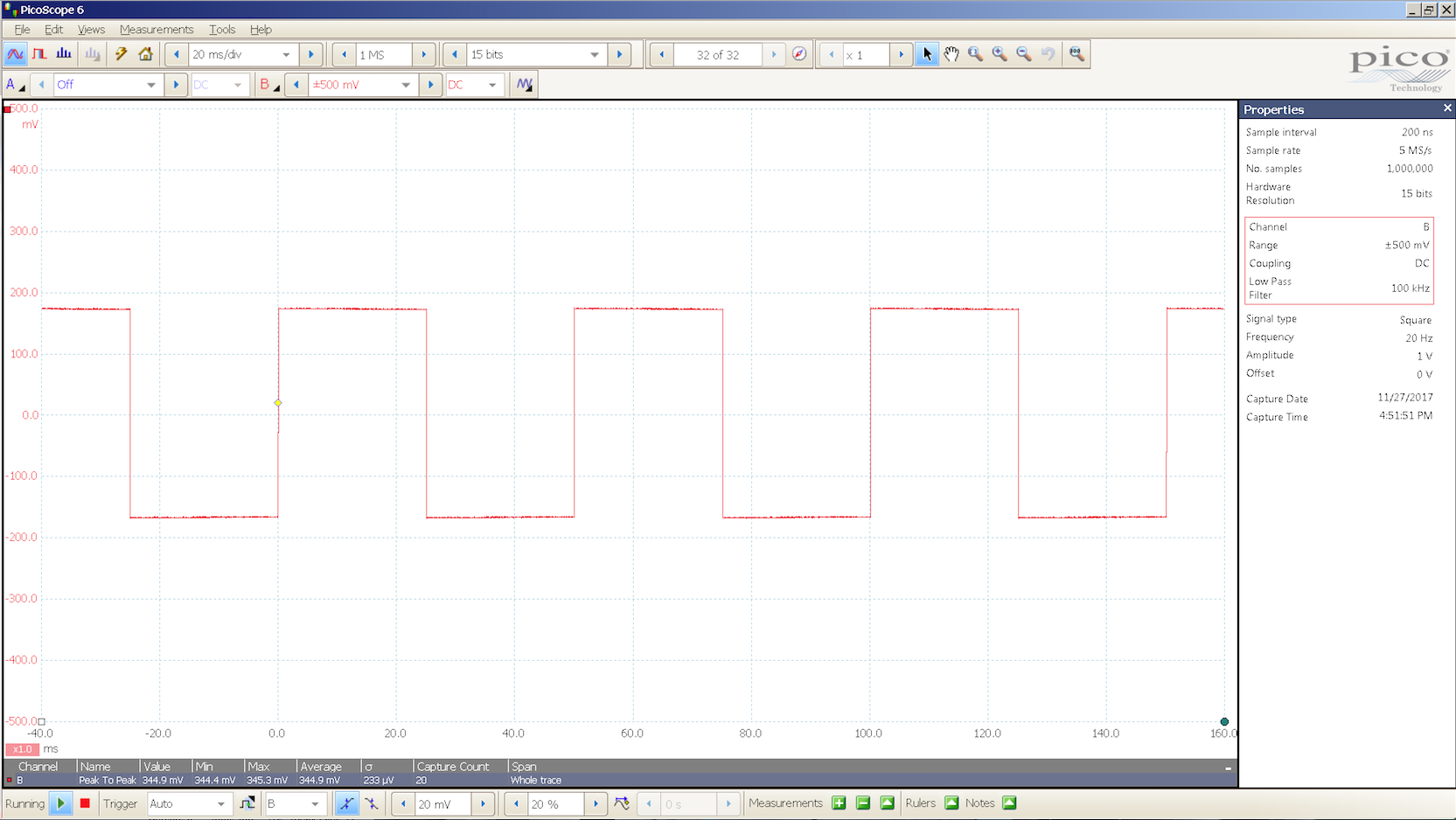
The last graph is the input wave form that the 800's are fed.
These examples are rough/early, response graphs, and I’m planning on a more thorough series of graphs which will make it easier to see the results this approach yields.
Note: a graph of a fully ’stock’ set of 800’s has even more overshoot than the 3rd graph shown here.
But first an analysis of the 3 graphs.
The top graph is my Gen-4 800's.
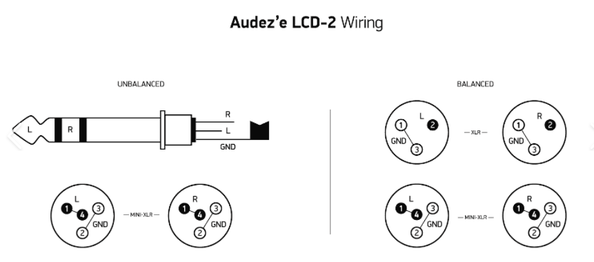
This set has already dealt with the trapezoid and protective screens on the outside of the driver, the inner dust covers have both been removed, they are hardwired with a SAA balanced cable and a rhodium 4pin XLR connector.
The middle graph was my early 'B' set of 800's that had minimal mods that include a cryo'd set of mondo gauge balanced cables that also has a rhodium 4 pin xlr connector, and the driver cover screens and dust covers had been removed.
The bottom graph is a near stock set of 800's with the inner fidelity mod, that have been hardwired as well.
One way to interpret these graphs is to follow the line (the trailing edge) that descends off to the right, and extend it up and to the left, until it reaches the leading edge of the original square wave signal.
In essence you are compressing the way the leading edge ‘looks’, because these graphs are using the highest degree of magnification available, which in turn makes them look ugly.
But this zoomed in view does show us the actual response of the driver when told to go from ‘at rest’ (0), to an arbitrary displacement and then stop and stay there, followed of course by returning back to the rest position to wait for the next cycle to repeat.
Notice, when you compare these 3 different responses, how that trailing edge line changes it's relative position (height above the x axis) with respect to each other, and to what a square wave should look like.
IOW the amount of overshoot during the Initial Leading Edge Response (
ILER) has been reduced as shown and in contrast to the change to the final displacement’s offset (height) from rest.
Another thing to notice is the total amount of resonant activity the driver makes before it stabilizes and doesn’t ‘wiggle’ any more as time progresses.
IOW not only how fast does the diaphragm stop wiggling, but also what the accumulation of all the wiggling adds up to, as shown.
Think, all of the area under all of those wiggles, combined, as an indication of generated acoustical energy.
This is an indication of the change to the amount of created acoustic energy where none is supposed to be in the first place.
This is a key aspect in helping all of the
C3 elements (Cohesive, Coherent, Coupling) become even further refined, along with several other previously described improvements to the overall SQ.
And during this project, once I zeroed in on this key aspect of performance that I found to be important, I tried to ascertain why this tendency to design in this overshoot, this deviation away from ‘ideal’, or at least a close approximation, is so common and used to the degree that it is.
Because there must be some benefit, but thus far I have not heard from anyone just what this benefit truly is, nor have I heard any reason that makes any sense to me at all.
But then asking the factory would probably not be a very fruitful approach.
However I may have stumbled over the reason for this, but I’ll need more time to evaluate just what I have truly stumbled over.
And with what I was hearing (Gen-4) and even more so now with Gen-5&6 , pretty much my primary motivation to take this to these latest levels (Gen-5&6) is just curiosity, because I’ve got a bad case of SuperDuperSuperGlue (my 800’s are glued to my head and I don’t even want to take them off) and a bunch of my other ‘colorful’ descriptors apply as well (
HB&W,
T3,
REALNESS etc.).
So my results at maximizing the 800’s involves tweaking the entire system that drives them,
AND taming that
ILER waveform to more closely match the input step waveform.
This approach also deals with the dreaded
tLFF, (the Listener Fatigue Factor) and tweaks the associated parameters with wonderful and surprising results.
DANGER!!! DANGER!!!!
YOUNG WILL ROBINSON DANGER
So this modification project has a few caveats and among them is…
We are fussing with the basic design of the 800’s and as such there is NO BACKUP, NO SAFETY NET of ANY kind!
DO this at YOUR OWN RISK!!!!!!
This will VOID your Warranty!!!!!!!!!!
If you screw up there is NO BACKUP other than yourself!!!!!!!!!!!
While repair parts are available they can be expensive (a set of drivers costs ≈$240 +S&H) and are usually backordered to Germany, think weeks)!!!!!!!!!!!!
IOW this modification requires a degree of commitment and responsibility on the owners part to assume ALL RESPONSIBILITY for the implementation of these mods.
Caveat Emptor, indeed!
Since this is getting long already I’ll end this 2nd part and resume in Part 3
End Part 2
JJ