blackgates (47uf NX hiQ or NX 100uf) for inside the case of 4G and 5G ipods (wont fit in the mini though) also BG (47uf NX hiQ or NX 100uf) for inside dock connectors. and for high end capped docks you can use any reputable brand, but Vcap (TFTF and VIOP), mundorf (SGIO or SIO), auricap, audionote if you are crazy or rich enough... the list goes on. the most common is blackgate though because they are great sounding and small witha reasonable price as well. just today I ordered myself some VCAP VIOP 3.3UF to use in a hammond case with piccolino wire. i'm putting several inputs and outputs on it too. adding TFTF VCVAP later down the track when the aussie dollar picks up a bit
IN
dock hardwired with piccolino
eichmann chassis mounted RCA's
chassis mounted mini
OUT
piccolino w/switchcraft mini
eichmann RCA
chassis mounted female mini
this dock is also going to be used with the bantam dac that i'm building plus any other DIY project that needs output coupling caps; thats why i'm putting all the I/O i'm leaving out the signal coupling caps in the bantam build and instead passing the signal onto this jack of all trades
I'm kinda of new to this iMod thing and I'm really interested. I currently have a 1st Gen iPod Mini that I'd like to use. My question is what's better and is it worth the hassle:
Analog Signal from Line-Out
In this case, I would just make a LOD cable and add some BG's between the L/R & GRD. THen just send the signal to my CMoY. Simple!
Analog Signal from DAC to Dock Connector
In this case, I would have to internally wire from the DAC straight to a "free" dock pin for both the L/R signals. Then build a LOD that would use those "free" pins & GRD, and of course add some BG's (inside it's cramped).
I guess what I'm asking is directly wiring to the dock connector really make a huge difference vs. just grabbing from the OE line-outs (of course using the same caps)? It really seems like a PITA to solder wire inside the mini, plus you'd need to remove some caps and inductors inside?
You wouldn't necessarily have to desolder anything from the logic board. It seems to make more of a headache and unnecessary risk of logic board bricking when desoldering those components. I'm thinking now that just about every diyMod should just short the components while leaving them on the board; the same would apply to your mini 1G. Depending on the wire, you could short the capacitors and inductors and just use the regular old pins 3 and 4 for audio output. ruZZ.il did this on his nano, but I wouldn't do it myself. You lose the versatility of switching in other LODs, say at a meet, and you'd have to go through the trouble of soldering to those itty bitty pins. Of course, do what you like since it's your diyMod.
Originally Posted by joneeboi /img/forum/go_quote.gif You wouldn't necessarily have to desolder anything from the logic board. It seems to make more of a headache and unnecessary risk of logic board bricking when desoldering those components. I'm thinking now that just about every diyMod should just short the components while leaving them on the board; the same would apply to your mini 1G. Depending on the wire, you could short the capacitors and inductors and just use the regular old pins 3 and 4 for audio output. ruZZ.il did this on his nano, but I wouldn't do it myself. You lose the versatility of switching in other LODs, say at a meet, and you'd have to go through the trouble of soldering to those itty bitty pins. Of course, do what you like since it's your diyMod.
Well that's what I'm wondering, is it "really" worth the hassle of soldering in a bypass from the DAC to the dock conector? Or just using the line-out pins with appropriate caps.
Originally Posted by bmwpowere36m3 /img/forum/go_quote.gif Well that's what I'm wondering, is it "really" worth the hassle of soldering in a bypass from the DAC to the dock conector? Or just using the line-out pins with appropriate caps.
the line outs -as far as an EE can see- still pass through multiple R/C & L/C filters as well as some kind of follower amp before it reaches the docking connector. So yes would be a good answer to that one..
Originally Posted by RinksCustoms /img/forum/go_quote.gif the line outs -as far as an EE can see- still pass through multiple R/C & L/C filters as well as some kind of follower amp before it reaches the docking connector. So yes would be a good answer to that one..
Nice I like that answer. So my next question is what's the best way to route L/R signals from the DAC to the dock connector? Do I just wire in a bypass and leave the caps and inductors on the board or do I remove them and then wire direct DAC dock connector?
I really don't like asking what seems like simple questions, but this thread is huge and I could only find one example of a mini.
Originally Posted by joneeboi /img/forum/go_quote.gif I'd go with shorting the caps and inductors. Put the caps in the dock.
So basically removing the caps & inductors and soldering the bypass between the cap pads and the inductor pads, correct?
I'm assuming I will lose audio thru the headphone jack when doing this. Any pics or posts that would aid me in locating these components to remove and bypass, thanks.
Originally Posted by bmwpowere36m3 /img/forum/go_quote.gif So basically removing the caps & inductors and soldering the bypass between the cap pads and the inductor pads, correct?
I'm assuming I will lose audio thru the headphone jack when doing this. Any pics or posts that would aid me in locating these components to remove and bypass, thanks.
The line out path to the dock and the headphone out are separate, so this mod won't affect your headphone out.
I think what Joneboi is advocating is that you NOT remove any components. When you remove the SMD devices, there is a risk of damaging the mainboard, so he is suggesting that you simply bridge them. For example, solder a small piece of wire, or maybe a resistor lead, around the caps and inductors. Essentially you create another path around the component. This would make your changes easier to "undo" if you later want to.
I'm not sure I agree with this method though. I understand that it will basically provide an alternative "path of least resistance" so the signal bypasses the internal component between the DAC and the dock. Joneboi, are you then also suggesting not to run a wire from the DAC to the dock? I thought the reason for removing the SMD components was to break that signal path, and then we added the wire to provide a "cleaner" path. So the traces, extra solder joints, and the bridges won't adversely affect the signal? If this is what you're thinking, you might be right. Maybe my reservations are just a psychological effect It seems like using my nice SPC wire will be better
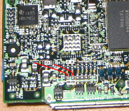
Well I desoldered what I hope were the right components (C53, C54, L7, L8, C69, & C70). So now where do I connected the upper cap pads to? Also using a solid copper wire good, 30 AWG?
Squares:
RED (C53) - Right Line-Out from DAC (~1.7ohms)
BLUE (C54) - Left Line-Out from DAC (~1.7ohms)
YELLOW (C69) - Dock Connector Pin 3
MAGENTA (C70) - Dock Connector Pin 4
So basically I just going to jump C53 to C69 and C54 to C70. Having removed the inductors and capacitors, from the line-out signal now leaves me in quandary. Looking a the Wolfson Datasheet, they show that this is how the "line-outs" should be connected before going to anything (amp or earphones):
Most iMods i've seen hear, IIRC, only use the coupling caps and not the resistors...
However when I measure between C53 and GRD (same with C54 and GRD) I'm reading ~100K ohms. And how does for coupling caps, BG NX 47uF bypassed with a (either Russian PIO or Vitamin Q) .047uF!
Ok, so I have been browsing this board and I was really interested in doing the mod myself. Unfortunately I only had an iPod classic which wouldn't work, so I went and bought a 5.5 gen off of ebay, and of course it broke the same day I bought it :T
The hard drive failed. I was wondering if the harddrive from the classic would be compatible with the ipod video?!?
Could I take the harddrive out of the ipod classic (80 gigs) and put it into an ipod video (it was also 80 gigs)
Any help would be appreciated
I found the exact specs of both hard drives, but these numbers don't mean a whole lot to me.
Anyone else have a better idea and willing to help??
This site uses cookies to help personalise content, tailor your experience and to keep you logged in if you register.
By continuing to use this site, you are consenting to our use of cookies.


 It seems like using my nice SPC wire will be better