Quote:
Originally Posted by joneeboi /img/forum/go_quote.gif
i) You don't necessarily need thin solder, but it is easier to work with.
ii) The finer the tip on your soldering gun, the better for this project. But if you're planning on using it for further DIY, don't get the finest tip as it won't be as versatile. Get a good temp-controlled soldering gun from Weller so you can have multiple tips for different soldering occasions.
iii) Anything finer than 26 AWG has worked so far.
|
Ok, I'll look...need cheap stuff..What type of wire is best, silver, copper? Does it matter?
Quote:
| Those are kind of pricey, though for a pair it won't hurt too much. Check 9.4.0 at post #1 for alternative vendors. |
I bought them already
Oh well..I bought 6 in case anyone needed them...or if I mod anymore iPods. =)
Quote:
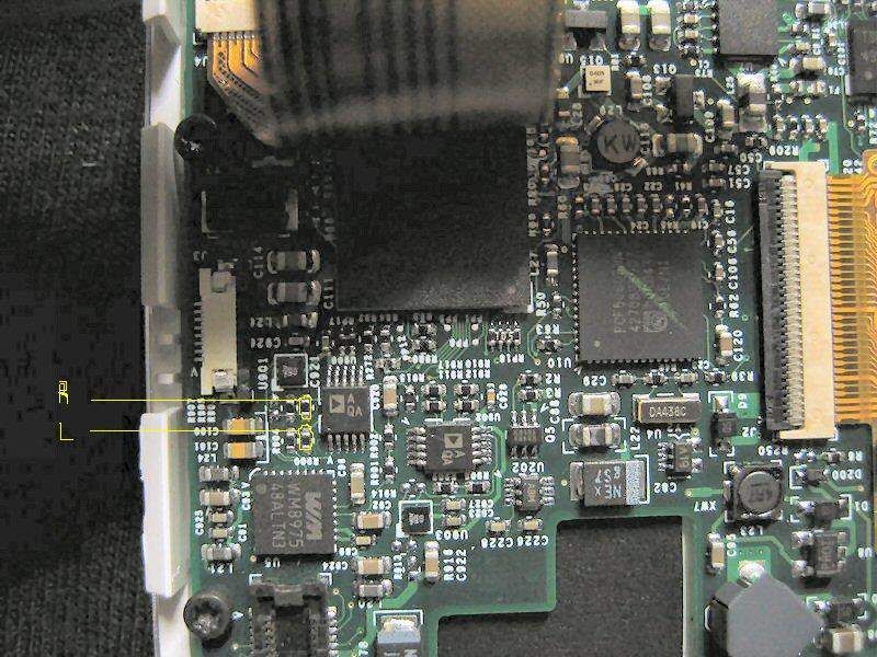
| In your image, the left rectangle is where you get the signal from. Desolder those resistors and test if the signal is working before you close up shop. The leftmost resistor is the right channel and the rightmost is the left channel. In the 4G click wheel non-photo, you have to desolder caps to get the signal, and they're placed right where the caps are in your image. But since we're dealing with the iPod photo, you take the signal from the resistors. Consult the following image, |
Ok, so in my image, the leftmost rectangle is where I should desolder the resistors, then does it matter what side I solder my wire to? There would be 2 points per resistor where I could re-solder back on, correct?
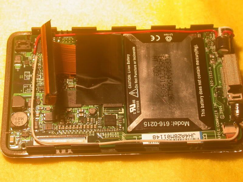
Now, looking @ KoKoKrunch's pic here :
He soldered the capacitors in different spots.
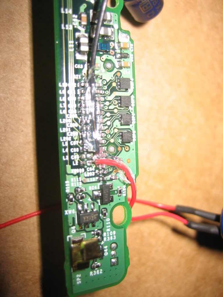
But, as I understand it, I don't need to use those two spots since I have a Photo 4G, I use the one in the left rectangle of my pic to solder the capacitors to. Then, I solder wire to the capacitors, then solder again to capacitors again and then to L2 and L3 spots.
This will then allow me to have audio out of headphone jack with clarity.
Is that correct?
Or does this mod I said above give me the sound out of the LOD? I'm confused again.
Thanks alot btw for the help!
Quote:
| If you're hoping to send the signal to the headphone jack, it shouldn't matter what is going on at the bottom connectors. But if you're still curious, the signal is sent to the pads labeled L2 and L3, with L2 being right and L3 being the left channel. |