The Apple diyMod: My Take on the Famous iMod [56k killer] Featuring 3G, 4G, 5G and nano 1G!
Dec 15, 2007 at 6:13 AM Post #226 of 3,220
Edited out!

Sorry Bobby, I assumed you knew how this mod worked...my fault. I understand what he is doing, but your question was worded kinda weird so I didnt understand what you were saying; jericho explained it in a pretty good way.
 
Dec 15, 2007 at 7:09 AM Post #227 of 3,220
Quote:

Originally Posted by wgr73 /img/forum/go_quote.gif
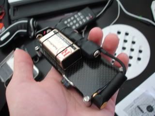
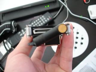
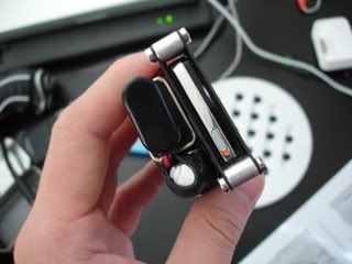
Well I couldn't squeeze everything in, but the tic tac container that joneeboi made up was a good one! Some of the first pics are of me assembling it, so it looks like a mess!

Sound Impressions: DiyiModNano

WOW! Thats all I can say. It sounds rediculously better than the headphone out, and even the lineout! The resolution has been upped by at least 5 times! I am in awe. I listened to a 128kbps song and it was that much better. You can really hear the low bitrate so be careful! I put my headphones back into the headphone jack just to tease and it sounded flat and muffled. This is just insane! And im not even using blackgates, im using another non-polar brand...not sure, I'll have to check. Here are some pics!!!!! Thanks joneeboi.


nice picts, i miss that post before...
eek.gif
 
Dec 15, 2007 at 7:10 AM Post #228 of 3,220
Quote:

Originally Posted by jERiCOh /img/forum/go_quote.gif
There is a little excel file I made to match caps to your amp. I dunno if it's gonna be useful to someone but I found it useful in my research of "boutique" caps. Enjoy!
smily_headphones1.gif


What is the right way to measure amp impedence? Just to be sure.

Look like my mini3 have 4000 ohm.
 
Dec 15, 2007 at 10:28 AM Post #229 of 3,220
Quote:

Originally Posted by joneeboi /img/forum/go_quote.gif
The RWA/ALO collaboration only happened with the iMod 5G. Further, the iMod nano 1G only happened once as a custom job for drp. As for the dock, checking out Apple iPod dock interface pinout and signals @ pinouts.ru shows that there are no unused pins. Aside from that fact, ALO takes the line out signals from the same place as every other analogue iPod dock. The iMod 5G dock simply replaces the dock's output, such as jERiCOh has shown us here. If you can figure out a way to get the line out feed straight from the WM8975 to the dock, then do share. You could route the wires to the dock, but I couldn't tell you too specifically how. Send the feed from C53 to pin 3 and C54 to pin 4.


Ok. Yeah I just realized what jERiCOh did. That's exactly what I want to do, but I'm not sure either. That would be the best solution for the nano in my opinion.
 
Dec 15, 2007 at 10:31 AM Post #230 of 3,220
Quote:

Originally Posted by joneeboi /img/forum/go_quote.gif
The RWA/ALO collaboration only happened with the iMod 5G. Further, the iMod nano 1G only happened once as a custom job for drp. As for the dock, checking out Apple iPod dock interface pinout and signals @ pinouts.ru shows that there are no unused pins. Aside from that fact, ALO takes the line out signals from the same place as every other analogue iPod dock. The iMod 5G dock simply replaces the dock's output, such as jERiCOh has shown us here. If you can figure out a way to get the line out feed straight from the WM8975 to the dock, then do share. You could route the wires to the dock, but I couldn't tell you too specifically how. Send the feed from C53 to pin 3 and C54 to pin 4.


Ok. Yeah I just realized what jERiCOh did. That's exactly what I want to do, but I'm not sure either how to do it either. Like you suggested I could just route the wires to pin 3 and 4. But will the original line out signals for 3 and 4 interfere with the signals from the WM8975? I think jERiCOh said we could cut the traces.
 
Dec 15, 2007 at 3:04 PM Post #231 of 3,220
Quote:

Originally Posted by CAvanessia /img/forum/go_quote.gif
Ok. Yeah I just realized what jERiCOh did. That's exactly what I want to do, but I'm not sure either how to do it either. Like you suggested I could just route the wires to pin 3 and 4. But will the original line out signals for 3 and 4 interfere with the signals from the WM8975? I think jERiCOh said we could cut the traces.


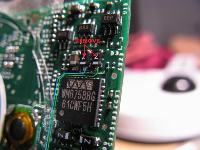
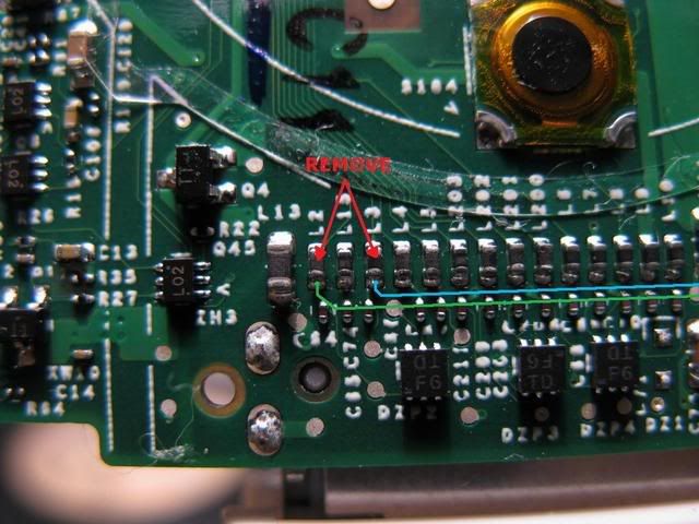
I was still hearing the click wheel when I was scrolling trough my library. It means that just installing the wires wasn't enough to get the signal from the DAC go straight to the dock connector. I had to remove the onboard capacitors and inductors as well to make the signal "perfect".

IMG_5689.jpg

IMG_5683.jpg
 
Dec 15, 2007 at 3:40 PM Post #234 of 3,220
Quote:

Originally Posted by vvs_75 /img/forum/go_quote.gif
Did you track the (C84 & C86) with millimeter from the DAC chip?
I tried on my first ruined board and couldn't!

The WM8975 is on other side of the board and look like the caps you using doesn't go the WM8975.

In any way as joneeboi said you need solder wires from the pads to the iPod's dock or phone's jack directly to make a difference.


Perhaps, I'm wrong; the C84 & C86 may be dec caps. Does anyone know what they are?

Moreover, I wonder why not short all the components in within signal path? Won't this be earlier than soldering a thin wire in those 1mm pads?
 
Dec 15, 2007 at 4:14 PM Post #235 of 3,220
Quote:

Originally Posted by dumbears /img/forum/go_quote.gif
Perhaps, I'm wrong; the C84 & C86 may be dec caps. Does anyone know what they are?

Moreover, I wonder why not short all the components in within signal path? Won't this be earlier than soldering a thin wire in those 1mm pads?


The reason to solder a thin wire is to bypass the even thinner circuit traces on the board. Plus by doing so you can use better conductors than what might be utilized on the PCB.

I've just checked C84 & C86, and it seems as though they output to the dock connector (which I'm guessing we already know). But that's about all I know. They seem to have some resistance when I measured them with the previous recommended soldering points of those tiny resistors.
 
Dec 15, 2007 at 4:24 PM Post #236 of 3,220
okay, I figured out why my 1g nano was making the whining sound. I forgot to connect the ground for the jack :p my bad.. the whining sound is now gone.

anyways, this is a bit off-topic, but just want to show you guys the mini-cmoy i made to go with the nano
DSC03235.jpg

DSC03236.jpg

DSC03237.jpg
 
Dec 15, 2007 at 4:24 PM Post #237 of 3,220
It wouldn't be easier because you'd have to find every single component that is in the signal path and short it, as opposed to soldering two wires to two pads. The latter isn't as hard as you think, whereas with the former you'd have to follow the traces everywhere which can be near impossible once you hit boards like the iPod video's where there are four layers of tracing, and then short everything which would somehow incorporate soldering to pads smaller than 1mm anyways. Not to mention troubleshooting would be a nightmare. By comparison, two wires to 1mm pads seems like a luxury.
 
Dec 15, 2007 at 4:29 PM Post #238 of 3,220
Quote:

Originally Posted by CAvanessia /img/forum/go_quote.gif
Ok. Yeah I just realized what jERiCOh did. That's exactly what I want to do, but I'm not sure either how to do it either. Like you suggested I could just route the wires to pin 3 and 4. But will the original line out signals for 3 and 4 interfere with the signals from the WM8975? I think jERiCOh said we could cut the traces.


If you want to have the diyMod nano 1G with a dock-connecting signal, then desolder the caps. If you want a diyMod nano 1G with a pigtail, you can keep the caps.
 
Dec 15, 2007 at 4:38 PM Post #239 of 3,220
Quote:

Originally Posted by ishtob /img/forum/go_quote.gif
anyways, this is a bit off-topic, but just want to show you guys the mini-cmoy i made to go with the nano


That's insane, ishtob. Did you make a pigtail with a CMoy in it? That's pretty cool, man. That's a first class nano. I'm impressed. Want to share more intimate details of the amp? At first I didn't know what I was looking at
smily_headphones1.gif
 
Dec 15, 2007 at 4:43 PM Post #240 of 3,220
joneeboi:
I didnt pigtail cause this ipod's original trace for the jack was messed up when i bought it off another member here, so The bypass/blackgate caps are hooked up to the jack. the second reason to hook it up to the output jack was I can still use my othe amps (pimeta, and the still in progress SOHA) if I wanted to.

as for that amp, it's just a really basic cmoy with the opa2132 opamp with a gain of 5, I'm still working on a design to use the OPA2227 with maybe a buffer, but I'm still a long way from getting a working design.
 

Users who are viewing this thread

Back
Top