The Apple diyMod: My Take on the Famous iMod [56k killer] Featuring 3G, 4G, 5G and nano 1G!
Dec 4, 2007 at 3:58 PM Post #91 of 3,220
Quote:

Originally Posted by drp /img/forum/go_quote.gif
Do you know (can you speculate on) which action caused the hairline crack in the ribbon cable? This would make for a good precautionary statement for anyone considering the Nano mod.


Sure, when I was putting it back into its slot it was hard to put in. Make sure when you grip the cable, you hold(I used needle nose pliers) close enough to the end of the cable to get enough leverage, otherwise it will bend(which I'm sure is what caused my crack).
 
Dec 4, 2007 at 5:11 PM Post #92 of 3,220
Joneeboi. Thanks for the response. I would like to squeeze caps inside (insane I know) if possible. Also, though I have an amp, I'll probably try to preserve lineout. I'm not too picky though. Good links on caps in your sig. Prob go with some blackgates. I think I'll wait till vvs 75 does a tutorial, just to make sure. Pretty confident about soldering skills, just never worked on an ipod. Thanks for everyones help though. This thread rocks.

I'm still really interested to hear first impressions on sound>?
 
Dec 4, 2007 at 6:38 PM Post #93 of 3,220
Here is a nano 1G disassembly tutorial.

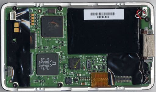
iPod Nano 1st Gen. Disassembly: Installing Battery & Logic Board - Removing Rear Panel (page 1/6)

I'm sure if Vinnie could have fit caps into the iMod nano, he would have done it. The nano 1G measures 3.5" x 1.6" x 0.27", or 88.9mm by 40.6mm by 6.89mm. The iMod's BG NX Hi-Q measures as small as 4mm x 7mm. It will be very hard to get that kind of clearance inside the super tiny casing. I'd try squeezing it underneath the battery. That would be my first guess, but I still doubt you could fit it there. Maybe you could drill two holes that will let the caps stick out of the casing. Just spitballing here, try at your own risk.

As for sonic impressions, I'll try my best. My setup is the 4G click wheel (with WM8975 CODEC) to 220uF Nichicon UPWs from Mouser to a Kobiconn 3.5mm stereo jack also from Mouser. The amp I listened most intently with was my Millett Hybrid MAX. The MAX's settings are a supply voltage of 27.0VDC with 12FK6 biased to 13.5VDC, Toshiba 2SC3422/2SA1359 BJT diamond buffers biased to 110mV. My boutique caps are 1000uF Panasonic FC at CA2 and CA7 with 5.1uF Solen bypass caps at CA8 and CA9. Mini-mini cable is generic. Headphones are Grado SR60s with rescreening, sticky tack driver mod, GS1K pads with glue mod. Indeed a very personal setup, nothing any of you might have, even within MHM builders and SR60 owners. My files are encoded to MP3 320kbps VBR.

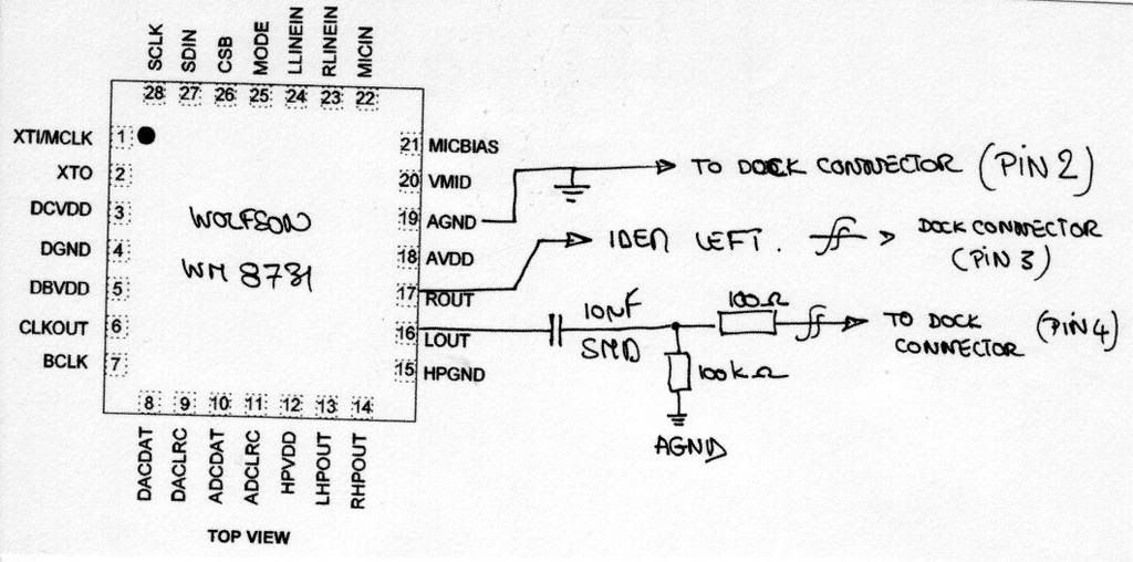
Plugging straight into the WM8975 (the datasheet says headphones can be plugged straight into the DAC if 220uF caps are put in series first), I listened to the very first time, as Nigel Kennedy played Sibelius' Violin Concerto in D minor, the performer's breathing. I had heard this sound before and I suspected it was hard breathing, but the clarity and intensity of his breath was very evident. I assure you I'm not exaggerating, as I've heard people exclaim that x piece of equipment allowed them to hear performer y breath and they could tell which nostril they were breathing from and performer y had a cold for the past two weeks. It's impossible to ignore this breathing. Switching over to some Hillsong's Savior King for some Marty Sampson singing In Your Freedom, I heard a portion of a drum beat I'd never heard before. It's just the snare going away on a regular system, but with the diyMod + MHM + SR60s, I could hear the hi hats going off in the distance. It was fairly not but overly subtle on this setup, but it's unnoticeable even in the car where we listen to this track plenty of times. The instrument separation was very precise, as I could switch from focusing on the drums and go to the acoustic guitar in one ear and then to the electric in the other ear to the piano in the back very smoothly. Loads of detail were available to me as though I were at a detail buffet and I could choose to listen to anything I wanted. On this setup, the highs sparkle quite nicely, balancing out the Toshiba BJTs' punchy bass. The corner frequency for this setup is ridiculously low, so bass rolloff isn't a concern (much lower than 1Hz). In fact, I think I've struck a nice balance between punchiness and extension. I prefer a fun, impactful bass, and this setup delivers it almost as well as I had heard with the Ayre Evolution CD player + Stax SR404 + SRM006tII listening to the same track. The noise floor is very quiet. Plugging in the iPod charger and pausing the music and turning the volume knob all the way up makes the AC noise only barely audible, so at listening volumes it's not a problem at all.

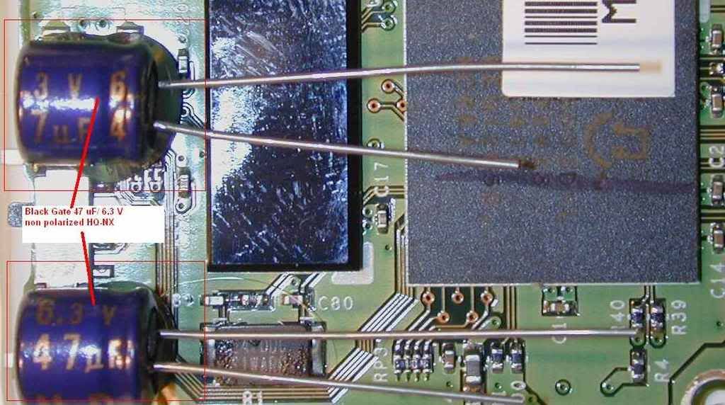
Overall, the take home message here is the separation. I really felt like I was onstage, walking between the performers to hear what they had to offer, although I'm sure volumes onstage are orders of magnitude larger than what I was experiencing. I like how everything meshes together right now, which is why I'm hesitant to even try the Black Gates. Even within the MHM builders, my setup is pretty far from what they recommend. My SR60s are one-of-a-kind, and I'm using Nichicons (220uF no less) as my diyMod caps. In other words, your mileage will vary greatly from mine as I'm sure no one will ever have this setup. That should be the caveat for a lot of reviews.
 
Dec 4, 2007 at 6:44 PM Post #94 of 3,220
Quote:

Originally Posted by joneeboi /img/forum/go_quote.gif
I'm sure if Vinnie could have fit caps into the iMod nano, he would have done it. The nano 1G measures 3.5" x 1.6" x 0.27", or 88.9mm by 40.6mm by 6.89mm. The iMod's BG NX Hi-Q measures as small as 4mm x 7mm. It will be very hard to get that kind of clearance inside the super tiny casing. I'd try squeezing it underneath the battery. That would be my first guess, but I still doubt you could fit it there. Maybe you could drill two holes that will let the caps stick out of the casing. Just spitballing here, try at your own risk.


I would LOVE to see that. Seeing as how it'd only BARELY stick out (we're talking in tenths of mm here), I think it'd be a viable solution. It'd also give it a pretty fairly techy look with caps slightly sticking out hinting to it's modifications. Execution would be key here as it would have to be cleanly drilled, etc.

I would donate my Nano to see this done. I would do this myself, but it would be weeks from now as I get some things sorted out, as well as the opportunity to buy some good solder and a new gun that's not complete junk.
 
Dec 5, 2007 at 1:44 AM Post #95 of 3,220
Quote:

Originally Posted by vvs_75 /img/forum/go_quote.gif
Then I drilled holes in cleaned from parts PCB and mounted the capacitors and resistors with point to point soldering. Be sure to use wire tubes on capacitors legs that goes through holes because the board are multilayered and even if you don’t see the tiny traces on surface they could touch them internally! Just to be safe. I used 100 ohm resistors in series and 47Kohm to the analog ground for each channel. You could skip at list series resistors and solder BG legs to the phone jacks legs directly. Plastic tray that supports the board has holes in it. If you use wires you can solder them through the holes. To make it easier you can just file the whole thing down as I did.


Just to be sure, does the text in bold mean that the it's possible to skip the 100 ohm resistors and just use the capacitors, or is both necessarily required?
 
Dec 5, 2007 at 1:58 AM Post #96 of 3,220
The resistors aren't necessary. The datasheet says to put two 100 ohm resistors in series after the caps, but that's only for protecting the DAC. lwaudio at ipastudio paralleled a resistor to ground after the cap, which is what vvs did too (you can't tell now that he removed that embarrassing picture
wink.gif
). I don't know how that affects the sound, so you'll have to ask them. I believe RWA omits the resistors as well. Here are the photos from ipastudio. You need to be a member there and then pass clearance to view them, so I just hosted them on photobucket.

Mind you, these photos are for the iPod 3G.

IP10.jpg


IP8.jpg


IP7.jpg


IP2B.jpg


IP4B.jpg
 
Dec 5, 2007 at 2:37 AM Post #97 of 3,220
QUOTE=firefox360;3467432]Just to be sure, does the text in bold mean that the it's possible to skip the 100 ohm resistors and just use the capacitors, or is both necessarily required?[/QUOTE]

Just look at RWA picture. Wires go right to the jack through holes in white plastic frame that hold the phone jack. No resistors! I removed mine too!

5-15-07-rwa_imod_2.jpg


DSC02423.JPG
 
Dec 5, 2007 at 2:51 AM Post #98 of 3,220
How do you guys think this mod compares soundwise to building an ipod dock connector to access line-out?

Also, hows the nano 1G mod goin vvs?
 
Dec 5, 2007 at 7:32 PM Post #99 of 3,220
When you say "straight out of the WM8975" is that the same as soldering to C86 and C87? Or does that literally mean you have to solder to the tiny pins of the WM8975 chip? Dumb question, but I've read the posts a couple times and still can't figure it out. Thanks.
 
Dec 5, 2007 at 7:43 PM Post #100 of 3,220
Either way. As long as you hit the signal path before the "-" side of the cap. (i.e. positive side of the cap...)
 
Dec 5, 2007 at 7:58 PM Post #101 of 3,220
Ok. Sweet. I'm using an two old lipstick containers strapped on the back of my nano for true rocket style status. I originally had one, but it wont lay flat, and plus I can use one for a perfect im716carrying case. The other will have the caps and a round headphone jack I found on smallbearelec.com part 0627. Pics to come.
 
Dec 5, 2007 at 8:31 PM Post #102 of 3,220
Quote:

Originally Posted by dcc84 /img/forum/go_quote.gif
When you say "straight out of the WM8975" is that the same as soldering to C86 and C87? Or does that literally mean you have to solder to the tiny pins of the WM8975 chip? Dumb question, but I've read the posts a couple times and still can't figure it out. Thanks.


I would remove all four caps 86, 87 and 53, 54 and then use 53, 54 caps pads.
If after modification you still can regulate volume with the click wheel it will degrade the SQ.

Ok. Bought the 1st nano, caps and all parts! The weather is sucks, so it could take few days longer to deliver all stuff!
frown.gif
 
Dec 5, 2007 at 9:17 PM Post #103 of 3,220
What I'm most worried about is taking the ribbon out. So far, I've just been trying to do it still connected through the very small pry spot. VVS if I do take out 53,54 pads, I will def. need to disconnect ribbon. Do you know how to do this? I can't really get a good feel for the mechanism by looking at it from this view.
 
Dec 5, 2007 at 9:40 PM Post #104 of 3,220
Quote:

Originally Posted by dcc84 /img/forum/go_quote.gif
What I'm most worried about is taking the ribbon out. So far, I've just been trying to do it still connected through the very small pry spot. VVS if I do take out 53,54 pads, I will def. need to disconnect ribbon. Do you know how to do this? I can't really get a good feel for the mechanism by looking at it from this view.


I don't have mine yet. Go to Youtube. There you will find lots of video how to disassemble your nano.
 
Dec 5, 2007 at 10:00 PM Post #105 of 3,220
dcc84, look at my pictures. You'll notice the black bar going across the ribbon cable slot, that flips up(both of mine are open in the pics). Just use a jewelers flathead screwdriver to flip it up. Its easy!
 

Users who are viewing this thread

Back
Top