Starving Student Millett Hybrid PCB Step-By-Step Build Guide
Aug 15, 2009 at 6:11 AM Post #18 of 81
Finished!!

All fired up and glowing - I used ocean-green LED's for this one.


Give your Starving Student time to burn in. I'm not an advocate of hundreds of hours like some claim for headphones, etc., but your Starving Student will definitely change tone in the first hour or two. When you first power it up, it will sound bassy, thick and "cloudy." Within an hour or two, the tone will have changed 100% - more detail, more transparency. Things will continue to improve over the next 12 hours, with subtle changes after that as more detail and transparency comes in.

The electrolytics and Wima caps take time to burn in - not hundreds of hours, but definitely over a day or two - that's a fact!

(I moved this down slightly after adding the wiring sequence!)
 
Aug 15, 2009 at 3:24 PM Post #19 of 81
Superbly done TomB , so what's next on the list .... a B22 for dummies
wink.gif
biggrin.gif
.

The forum needs more of this type of thing for those who are starting out ( and even for those that aren't) , again WELL done.

..dB
 
Aug 16, 2009 at 2:54 AM Post #20 of 81
Quote:

a B22 for dummies
wink.gif
biggrin.gif
.


Do it, I dare ya.
smily_headphones1.gif


Great guide, the more people with Starving Students the better. A great little amp, I love mine. And if this guide was around before I might have actually built mine! Lucky Aussie DIYers are friends.

Anyway, a great guide.

Cheers!
 
Aug 17, 2009 at 11:52 PM Post #21 of 81
Great guide tomb. I'm on step 4 right now
smily_headphones1.gif


BTW for the drilling of the sockets, it is much much easier/faster to drill from the bottom. If all pins are like mine, a 1/8" bit takes about 30secs to drill the bottom vs a few mins to drill the top part of the pin.

Just to point it out.

I'll try to finish my amp tonight.

Best,
Georgi
 
Aug 18, 2009 at 11:52 AM Post #22 of 81
Thanks for the kind comments, guys!
smily_headphones1.gif


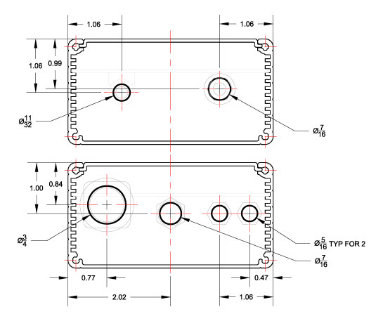
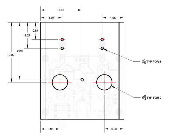
Since we're out of cases for the moment, I thought I'd re-post the drawing details to finish the Hammond 1455N1201 case for the SSMH PCB:

SSMH-1455N1201-EndPlates.jpg

SSMH-1455N1201-TopPlate.jpg


The only caveat to these drawings is the 3/4" hole shown in the back plate for the power switch is actually 0.79". You can auger out the hole slightly larger with a 3/4" bit (preferrably the 3/4" position on a step bit) or use a pocket knife to whittle a few slivers out of the hole to get the additional 0.040".

Oops - also, the spacing between RCA jacks went to the industry standard 18mm. So, that 1.06" dimension changed. *Sigh* I'll fix this tonight.

I will link these to some full-size PDF's tonight that you can use as full-size patterns.


EDIT: Sorry - I forgot to post the PDF templates (right-click and select "Save As" to download):
Top Plate - SSMH-1455N1201-top.pdf
End Plates - SSMH-1455N1201-endplates.pdf
 
Sep 7, 2009 at 4:47 AM Post #24 of 81
Bookmarked! I was thinking about building one as my first DYI amp project, instead of reading a thousand pages of the "official" Starving Student thread to seek ideas, this thread simplified it into an easy step by step guide. I will definitely get into it tomorrow, hopefully I can get it started by next weekend.

Thanks Tomb!
 
Sep 7, 2009 at 11:18 AM Post #26 of 81
I just received an order of Navships wire and I'm now going to rewire my SSH (kit from Beezar). I'm wondering (Yes, I've re-read this thread) if I should tin the wires that will be inserted into the terminal blocks, or just insert stripped wire directly??? Also, how hard should I tighten the screws?

Thanks,
 
Sep 7, 2009 at 12:38 PM Post #27 of 81
Quote:

Originally Posted by sandbasser /img/forum/go_quote.gif
I just received an order of Navships wire and I'm now going to rewire my SSH (kit from Beezar). I'm wondering (Yes, I've re-read this thread) if I should tin the wires that will be inserted into the terminal blocks, or just insert stripped wire directly??? Also, how hard should I tighten the screws?

Thanks,


If someone is picky about cabling and wire types, I suppose it may bother them to tin the ends on the signal wiring. When you do that, you're clamping down on the solder with the screws, not the wire. You could use that argument with every soldered joint that's on the PCB, however.
wink.gif


I've done both and haven't noticed any difference in sound quality. Actually, not tinning may improve the repeatability. It seems that tinning the ends causes them to be more susceptible to breaking over the long haul, but that could just be my imagination. I've tinned both the ground wires and soldered them together before, but it seemed to me that the resulting large lump made worse contact than without soldering them together. Perhaps when you tin, you should keep the wires separate and do it as lightly as you can. That's what I've been doing lately.

In either event, I screw down the screw as much as I can - using only a small precision screwdriver, though. There might be some of us who could use a large screwdriver and torque the terminal blocks right out of their soldered pads - or worse.
wink.gif
wink.gif
 
Sep 27, 2009 at 8:08 PM Post #30 of 81
Just finished mine last night(finally got all the parts). Had a little scare when the first time I powered it up one socket wasn't firing. Turned out the pins weren't making contact within the socket, luckily that was an easy fix.

Sounding great so far, only issue is the volume pot which is very right biased when at very low volumes.

I'll post pics if I have time. I ended up using a different heat-sink than the 'spec' and it works, and I think looks, better.

Only took a day and a bit to finish the whole thing. In all, a very quick, easy project.
 

Users who are viewing this thread

Back
Top