the_equalizer
1000+ Head-Fier
- Joined
- Jul 5, 2009
- Posts
- 1,138
- Likes
- 70
Just look for beezar.com. They sell Millett kits. I built my MiniMax about a month ago and oh man.. is it a fun build and a sweet amp!
cheers!
cheers!
| Originally Posted by the_equalizer /img/forum/go_quote.gif Just look for beezar.com. They sell Millett kits. I built my MiniMax about a month ago and oh man.. is it a fun build and a sweet amp! cheers! |

| Originally Posted by netsky3 /img/forum/go_quote.gif Nice but too expensive
|

| Originally Posted by tomb /img/forum/go_quote.gif Compared to a Starving Student, yes, but even a Starving Student is too expensive when compared to a CMoy. The best that you can hope for is that there's a proportionate increase in performance at each level. I'll leave that judgment to others, though.
|
| Originally Posted by Llama16 /img/forum/go_quote.gif There are almost none here mate :S I'm with the exact same problem here. Import taxes and shipping is just killing me, so I end up spending close to double the US price for a project. I think there are such projects around, but it might take some searching. Maybe the YAHA, it's not a highend build at all but it's a great compact, fun and learning scheme to build. I'm planning on doing that myself one day soon. |
")


Sorry guys - looks like I forgot to include the entire wiring sequence. Here it is:
Coming down the home stretch!!
We've finished it all except for the endplates. What's really nice - there's no work at all on the front plates. Once you slide the assembly into the case, that's it - the endplate is already drilled to match the volume pot shaft and the headphone jack.
The back plate is not as simple, but still not too bad. I get discouraged at this part, though, because to me, wiring is so tedious. What's nice and makes up for that, though, is that you don't have to drill the holes through the back plate and worry about dimensions, hole sizes, or whether it will all fit - it's already done!
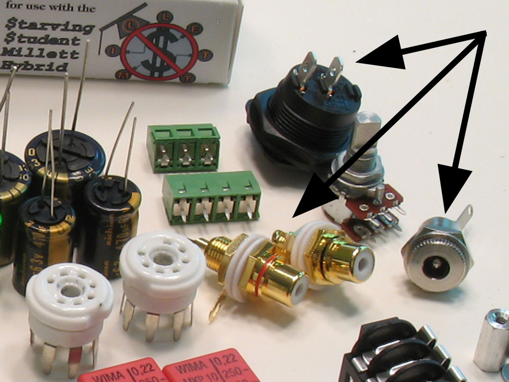
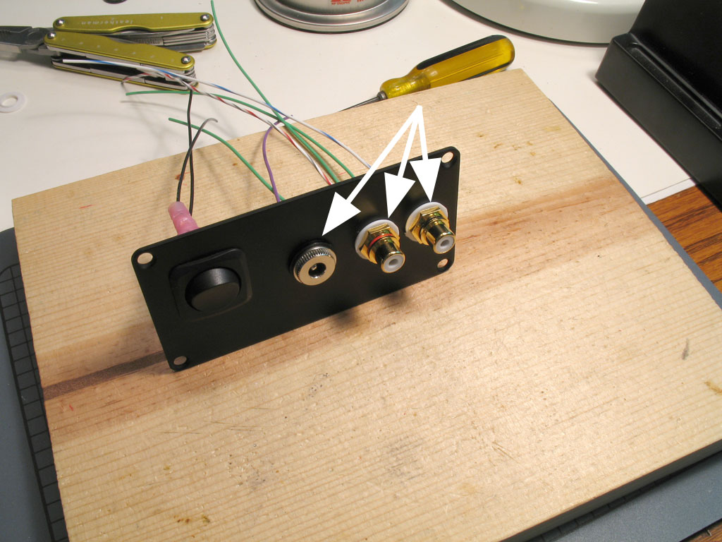
So, given that, the only thing we have to worry about is the connectors on the back plate. These are the Power Input Jack, the Power Switch, and the RCA Input Jacks. These are pictured here in a blowup of our kit parts layout shown way back in the earlier posts:
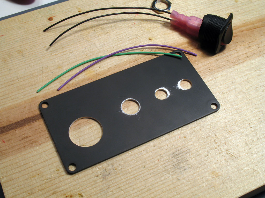
22. Install the Power Switch -
The power switch, while rated for much higher voltage, is plastic. Thus, it will melt enough that the mechanism may be damaged if you use a soldering iron to connect wire leads to the tabs. Instead, use a couple of fast-on connectors as shown here. These are available in every hardware store. In fact, the ones shown here are for much larger tabs, but they work fine for the power switch, regardless.
Be sure you crimp them so that the wire is snug. Pull on it and work it back and forth to make sure you have a good connection. I have to crimp it in two places, but maybe that's because I use the cheap tool shown in the photo.
Before we install the power switch, we'll want to prepare the back plate for the connectors. As with the case lid center hole, we want to scrape the anodizing away from the holes so that the connectors' negative connections will make contact with the case. Negative = Ground in the SSMH, so again, our ground resource will be increased when we do this. Just an FYI, but the RCA jacks fit snuggly enough that the edges of the drilled hole may be sufficient to provide contact. Still, if you're scraping/filing anyway - might as well do them all (except for the power switch - that's all plastic, so it won't do any good).
Note - be sure you know which side is which! The outside of the endplates have counter-sunk mounting screw holes. That's the absolute indicator - do your filing/scraping on the other side. The counter-sunk part of the holes are the outside.
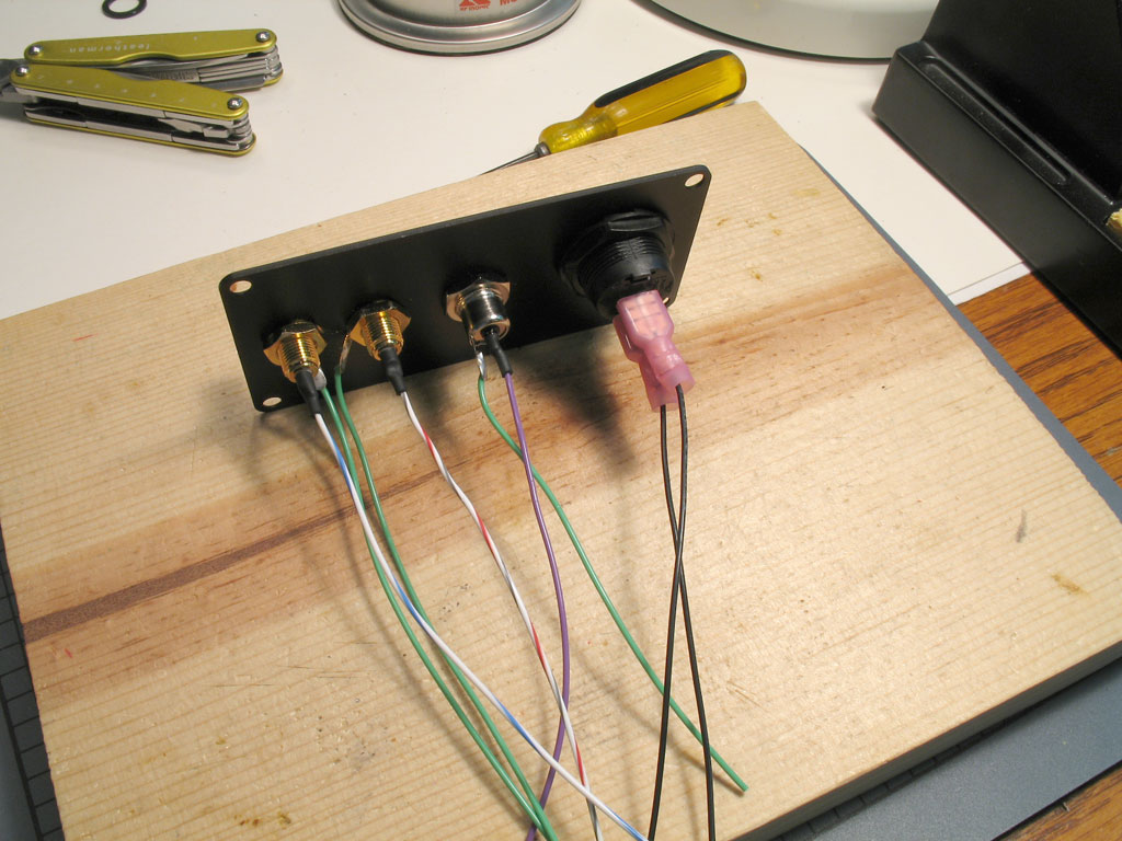
23. Install the Power Input Jack, the RCA Jacks -
Similarly, install the power input jack and the RCA jacks. Both require soldered connections, both ground and non-ground (or signal). The pic shows my usual workspace once I start wiring connectors - all h*ll breaks loose and the whole table turns into a mess.
In the photo, we can see the power input jack already wired and screwed into the back plate (more on that later). The power switch has already been installed on the back plate, and I'm in the process of finishing the wiring connections on the RCA jacks.
Here's a glamour shot of my soldering one of the ground leads on the RCA jacks. Some use a single ground wire and solder it to both tabs of both RCA jacks. However, I think two ground wires - one soldered to each tab separately works better.
The backplate finished with all connectors installed and the wire leads soldered. Note that when measuring the length of the wire leads, insure that you have enough slack to move the back plate up and over the main case body - this is the way that dis-assembly will be done. Also, note that the signal wires from the RCA jacks must be much longer to reach the input signal terminal block.
An outside view:
Note the insulators on the RCA jacks. Actually, the RCA jacks are best without insulators. As shown in the photo previous, there are no insulators on the inside - this is so the RCA jack grounds can make contact with the case. On the outside, the insulators are purely cosmetic. You'll find that it's almost impossible to plier the jacks down from the outside without scratching a circle into the backplate finish - the insulators will protect the finish and allow easier tightening.
With the power input jack, the hole is purposely sized larger than needed. This is because Radio Shack makes a similar power input jack that's larger in diameter. I left the hole big enough in case some want to use that jack. The jack in the kits will benefit from an additional finishing washer - simply use one of the washer/spacers that come with the headphone jack - not all of them are needed for the headphone jack.
24. Install Wiring and Back Plate -
Trim the wire leads to length if needed, but remember, there's a huge space behind the PCB - plenty of room to take up slack. The back plate must be able to move up and over the main case extrusion for convenient disassembly, so quite a bit of slack is needed.
Note also that the input signal terminal block is quite close to the sides of the case when assembled, so bend the wire leads at a 90 degree angle next to the terminal block and trim to fit. This makes it easy to obtain enough clearance for the input wiring. I like to braid mine in a Litz braid or similar, but I'm not sure it means anything over this distance.
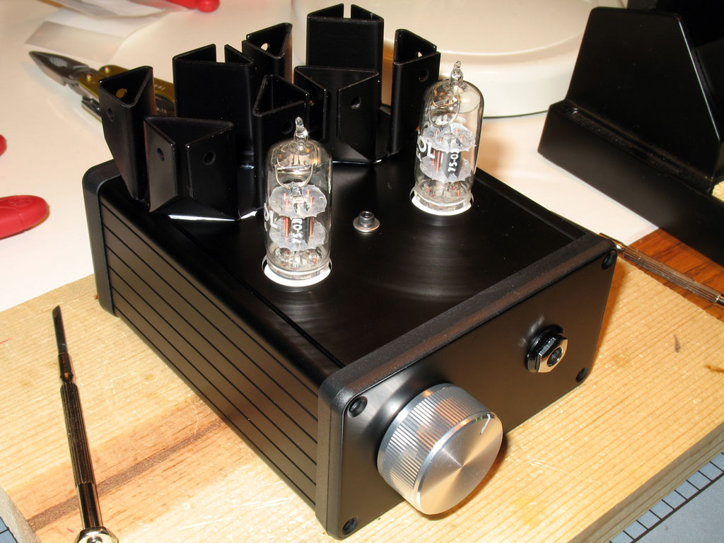
25. Assemble the Amplifier -
Hey! We're done!
Be sure to use the endplate bezels. Don't worry - you can slide the bezel over an endplate even when the wiring is connected. For the front plate, use one spacer on the headphone jack behind the endplate - that should be sufficient for spacing.
Pictured here, I've assembled it without the screws. If everything works, I'll disassemble it, tap the case holes and use 6-32 machine screws. That's not really necessary, though, the supplied Hammond screws will work fine - but don't use them until you're certain the case and the amp all work fine.
Back view:
And we add the volume knob - the idea is to get it as close to the endplate without scraping anywhere in its travel. This may be sometimes more difficult than it sounds - it depends on how well you aligned the volume pot when you soldered it way back when.

aww that looks nice!!! Can I buy one from you cuz i got only pair of dumb hands and a art brain lol
tomb,
I just finished building one of the latest kits. It was a great project for a beginner and I wanted to say thank you for this great tutorial. It made the project fun and the amp sounds better than I expected!
- Luke
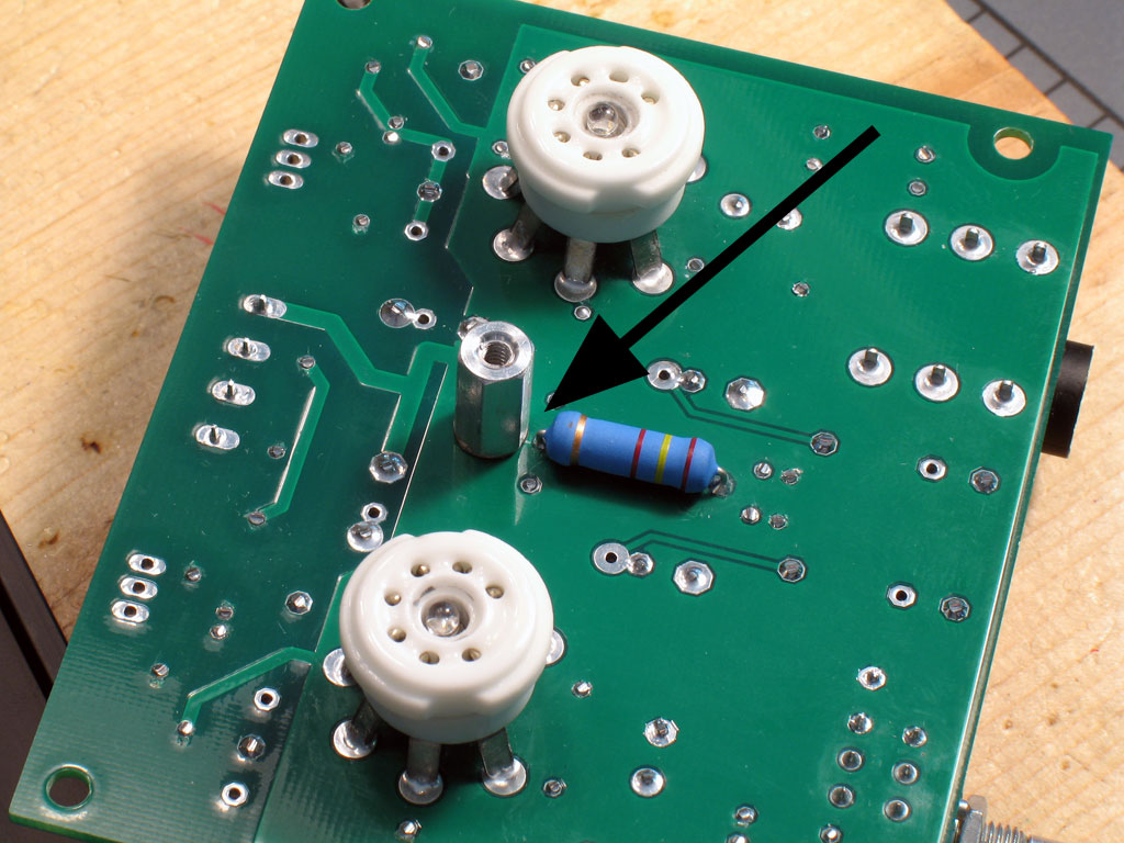
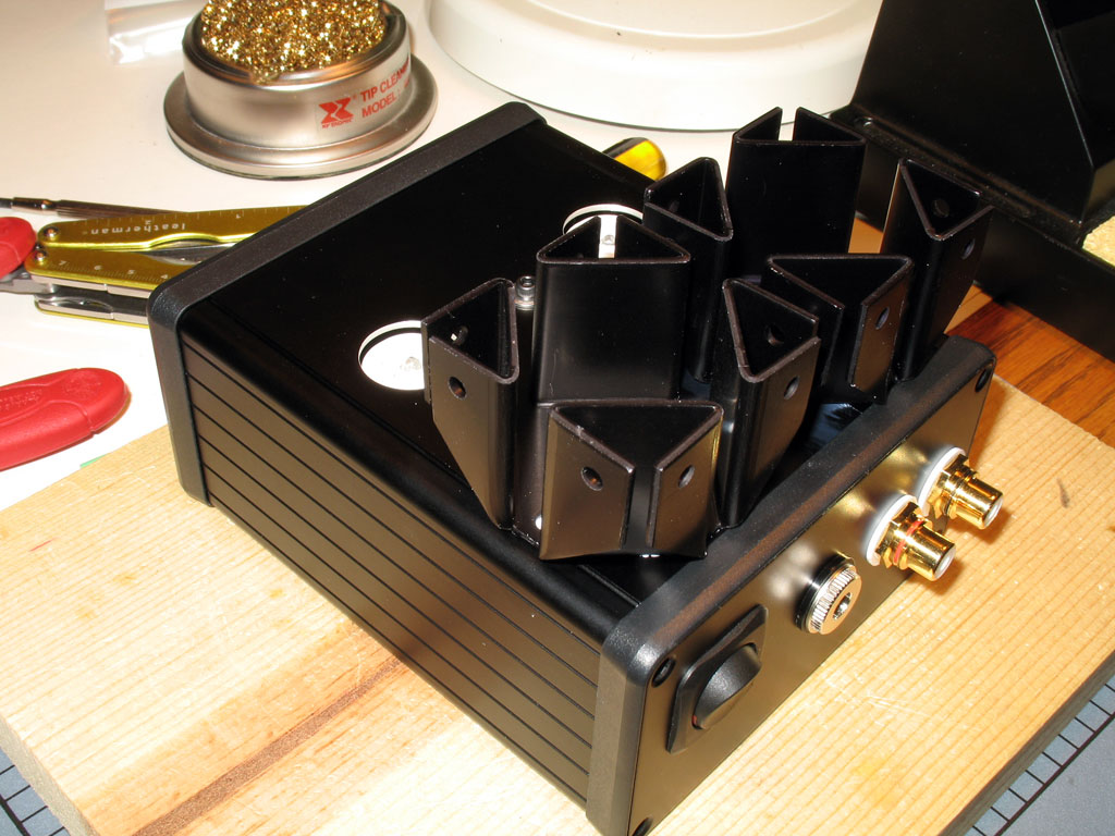
Here is the standoff assembly. This will be provided in the kit with several washers. At least one washer is required for spacing along with the standoff - perhaps two. The only caveat to this you'll see in a moment. There are some smaller washers you can pick from and you'll want to use those next to the PCB, or you may short the standoff against the tube LED resistor - more on that later.
This is critical!! Note the spacing between the standoff, washer/spacer and the tube LED resistor lead. Be certain that you have some space here as shown. Otherwise, disaster will ensue. Note also that the flat side of the hex standoff is also facing the resistor lead. This is an additional insurance that a space is maintained. Note that a small washer must be used here - a regular sized flat washer will contact the lead, so don't use one. Nevertheless, the spacing with only the standoff is not sufficient, so some additional spacing is needed and the small washer provides that.