


holland
Headphoneus Supremus
- Joined
- Jun 15, 2007
- Posts
- 2,210
- Likes
- 22
You're very welcome, runeight. It was interesting and a pleasure.


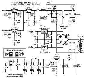
| Originally Posted by FallenAngel /img/forum/go_quote.gif So do I take out Q1P or leave it in? |
| Originally Posted by FallenAngel /img/forum/go_quote.gif So do I take out Q1P or leave it in? |
| Originally Posted by runeight /img/forum/go_quote.gif actually may be somewhat detrimental to the PS behavior. Hence its removal in the final design. |
| Originally Posted by holland /img/forum/go_quote.gif I think I missed that. Can you expound on it? Thanks. |


