


tomb
Member of the Trade: Beezar.com
- Joined
- Mar 1, 2006
- Posts
- 10,891
- Likes
- 1,066
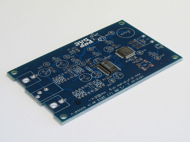
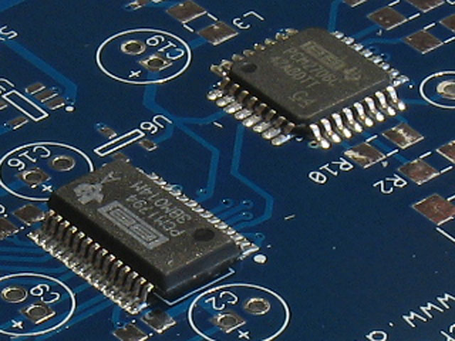
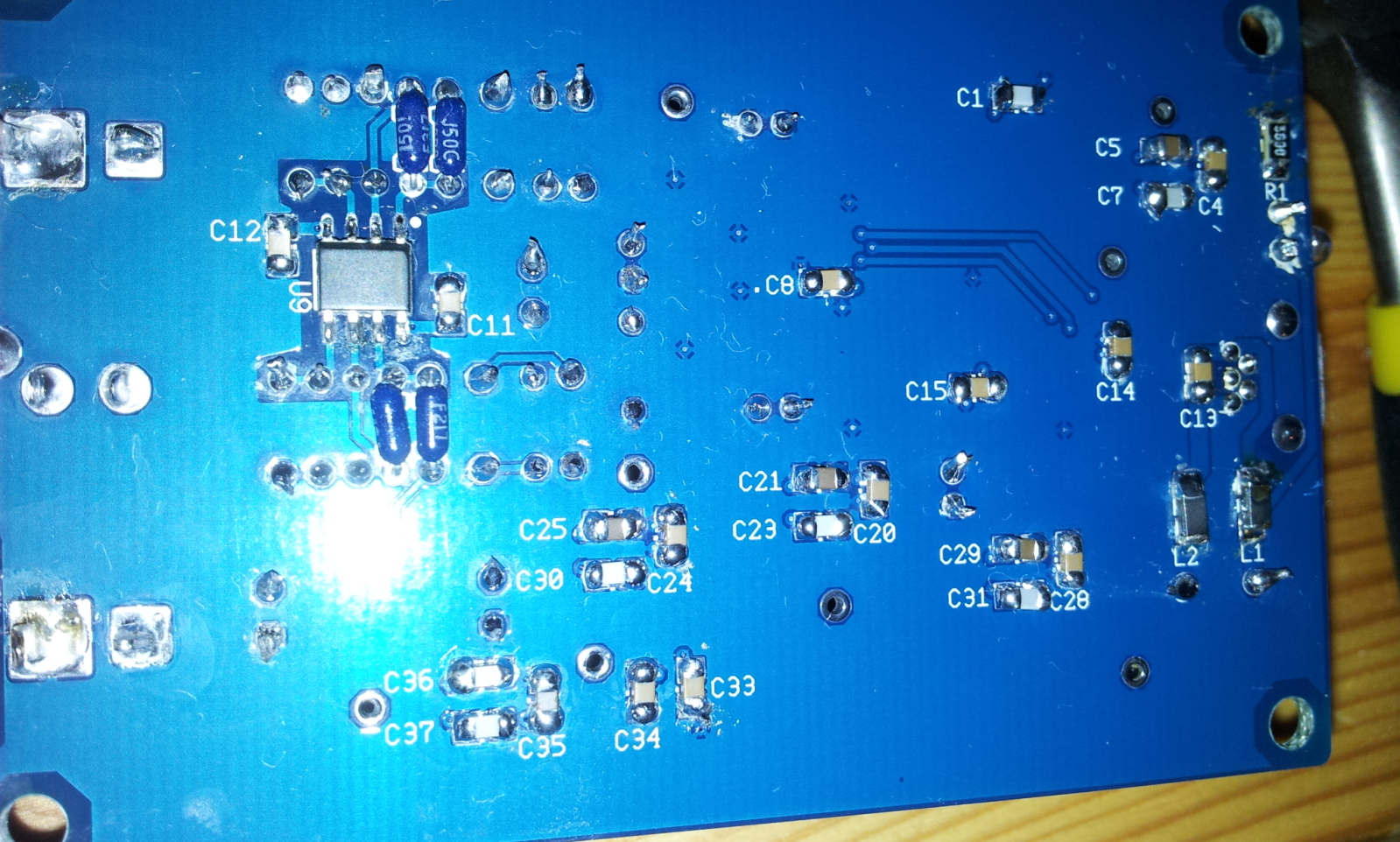
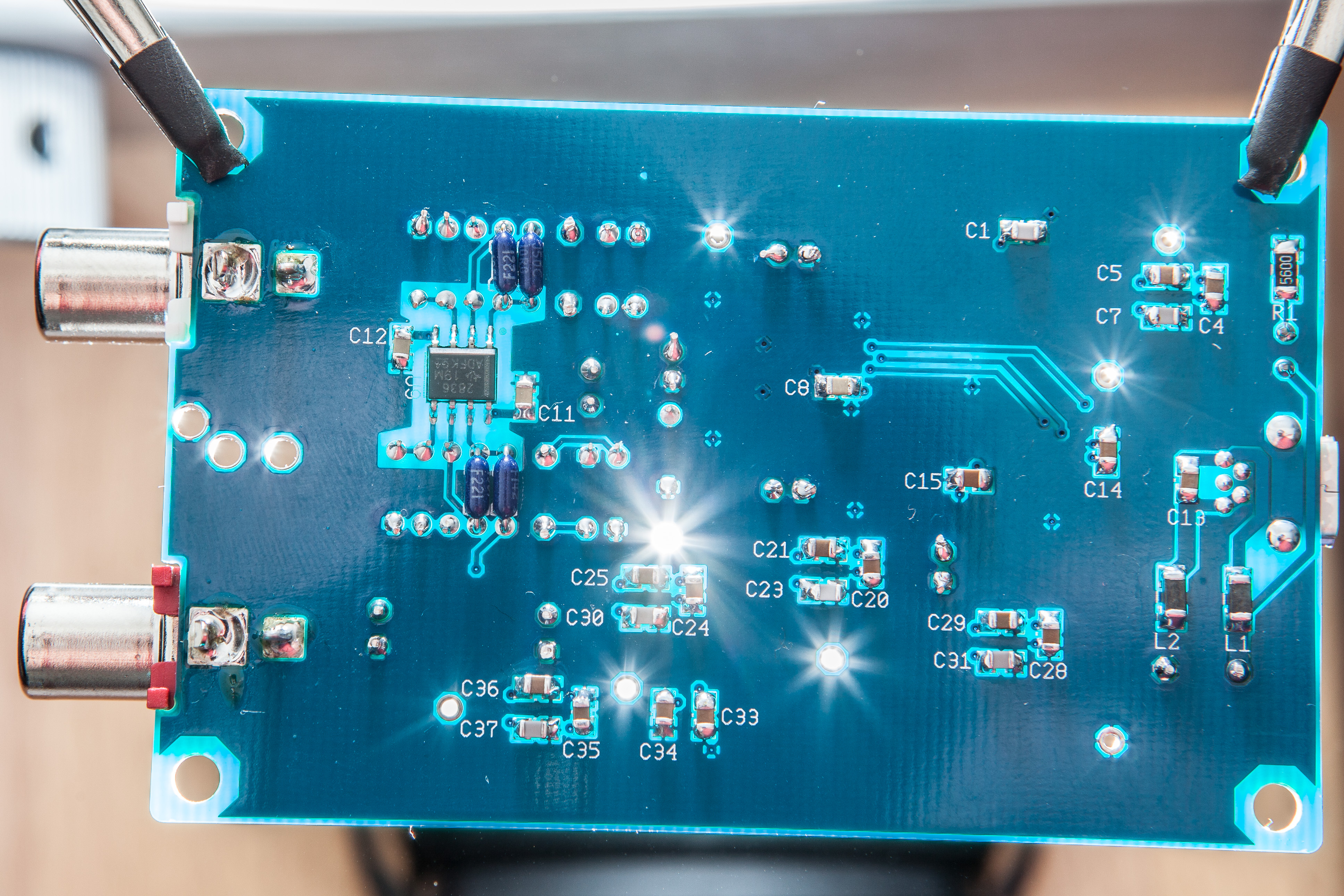
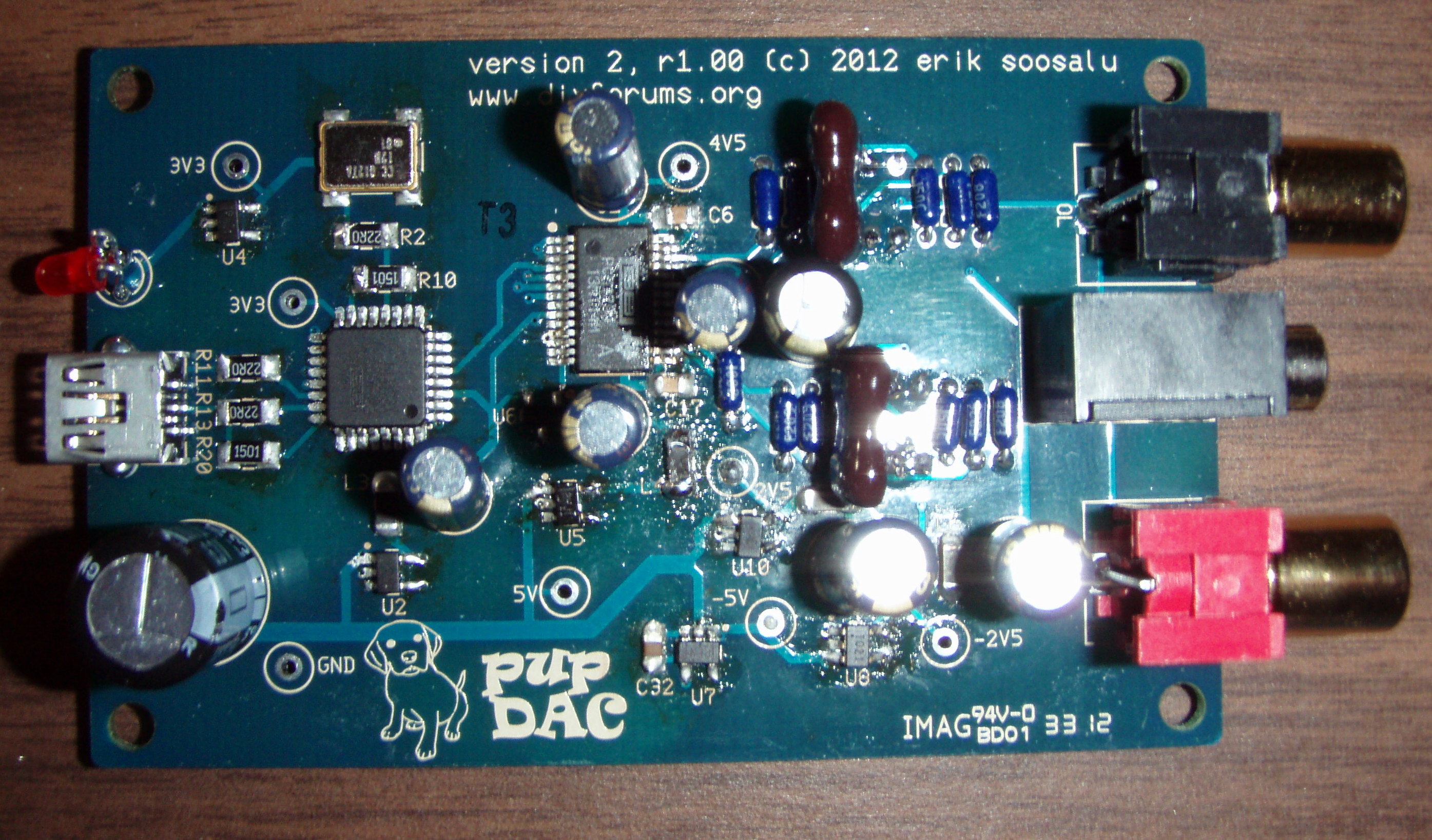
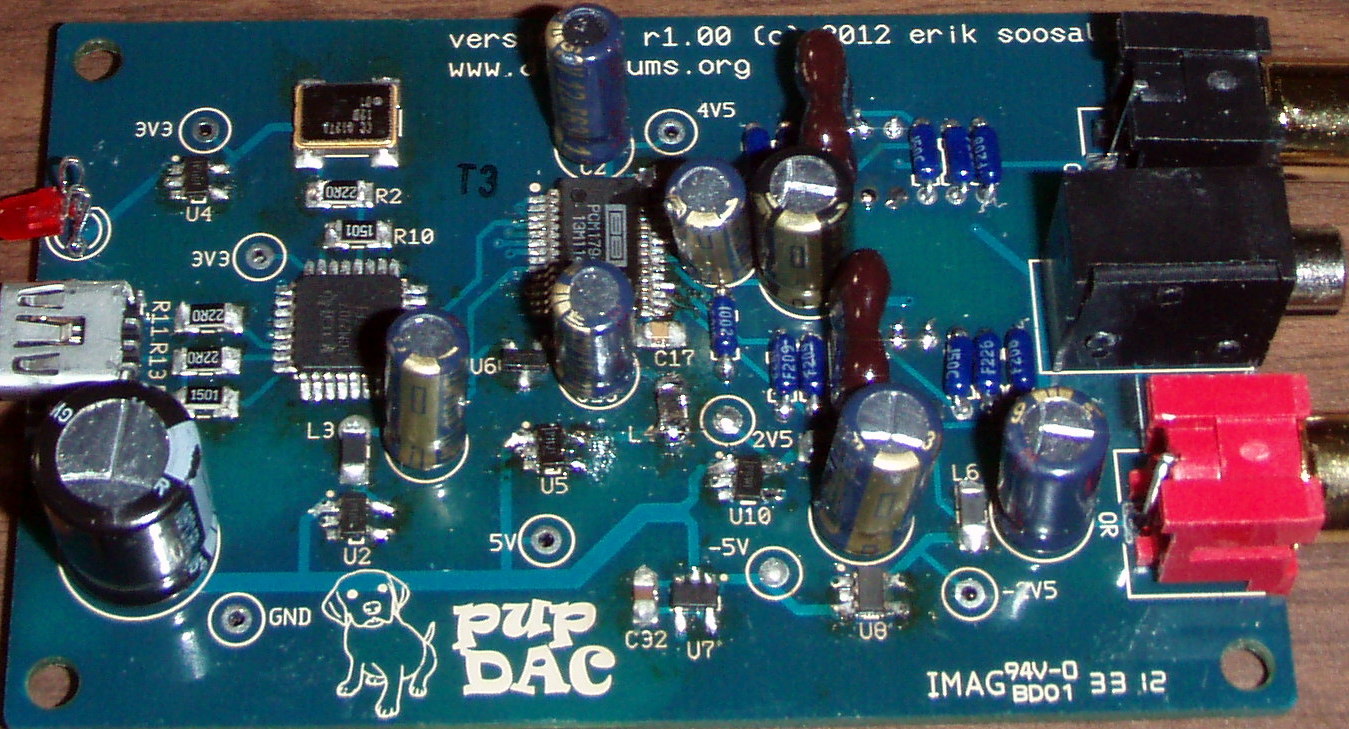
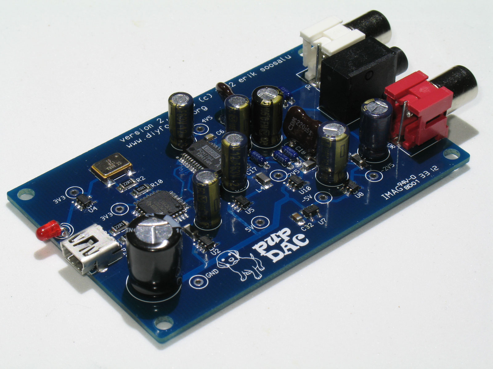
Once again, here are a couple of pics of the finished, trimmed, cleaned, and rinsed PCB.
Top:

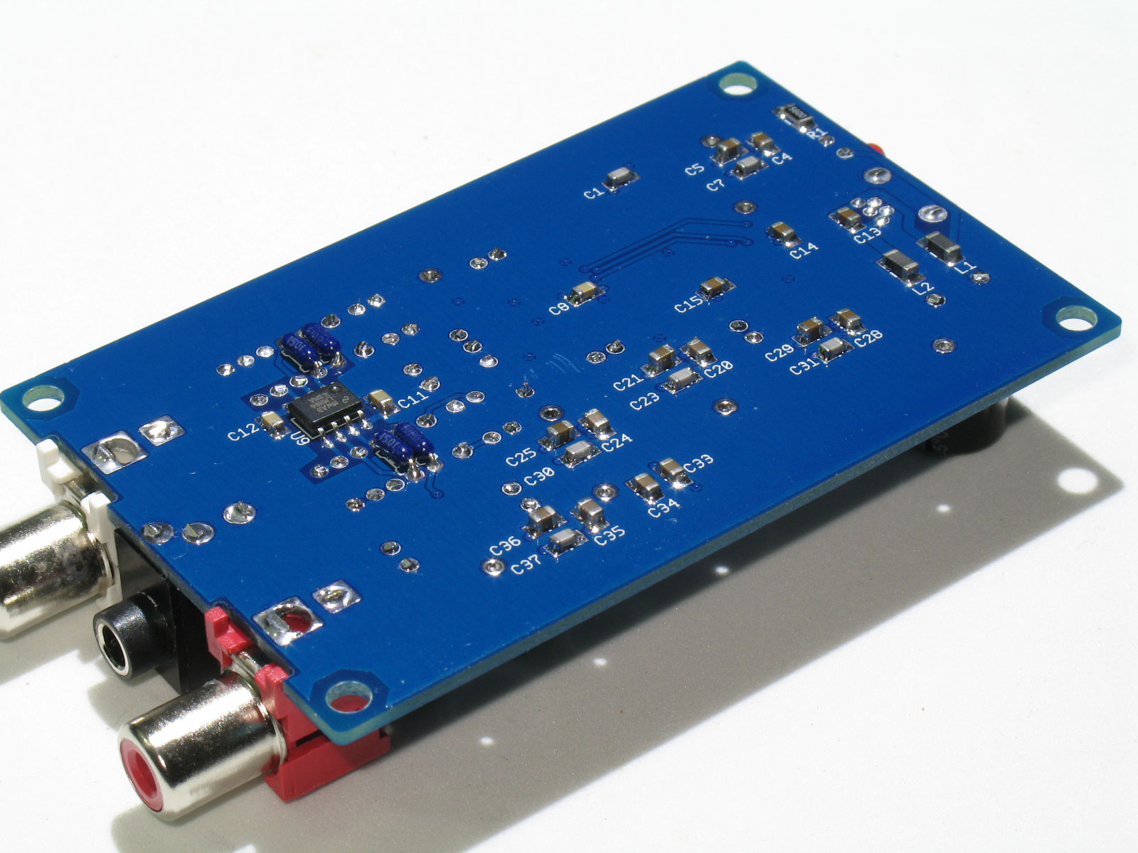
And bottom:

Note that the tabs are neatly trimmed for the RCA jacks and stereo mini-jack. The PCB will not fit into the case with these tabs remaining in place! The mini-USB jack's tabs/leads are already short enough - they barely fit all the way through the PCB holes. So, no trimming needed there. The rest of the trimming was the capacitor leads, the LED leads, and the resistor leads.
Casework is next!
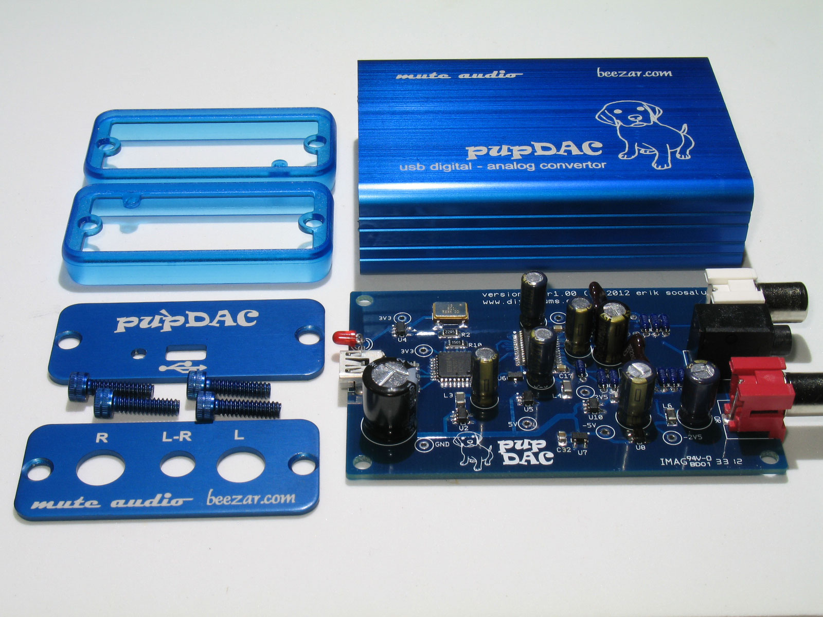
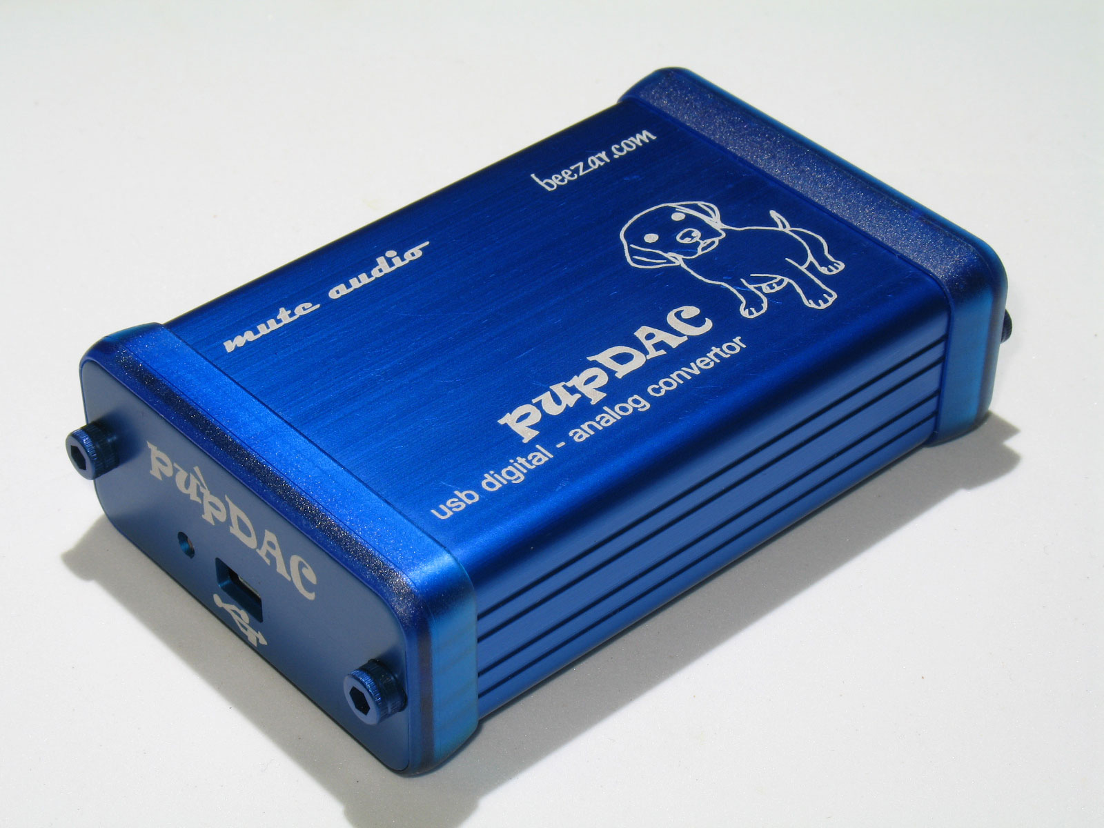
As mentioned, the pupDAC is designed specifically for the Hammond 1455C801 case (or 1455C802 with plastic endplates). We have designed a special machined version from Hammond with Beezar-anodized blue and laser-etching. Four screws are all that's needed for final assembly!

Those are special blue-anodized aluminum socket-head cap screws. If you build your own, remember that the Hammond case does not come tapped. Aluminum screws such as these will strip in short order if you haven't tapped the case. Hammond uses 6-32 screw sizes as a standard with their 1455 series cases. The ones shown here from Fastener Express are 1/2" long and work quite well on the tiny pupDAC case, but it must be tapped. Hammond supplies some inexpensive self-threading phillips head screws, but in silver, they're not nearly as pretty as these.

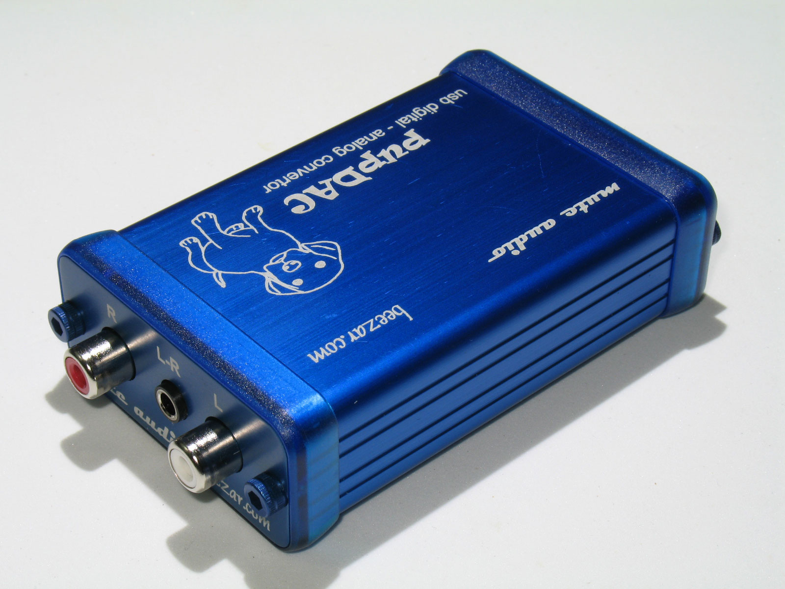
Here is the finished pupDAC completely assembled. It's your choice on whether to use the transparent-blue bezels. The endplates will fit either way. The tip of the mini-USB jack and the tip of the LED are flush with the outside surface of the endplate if you don't use the bezels - that's the only difference.


Yay!! I made it create a 2nd page!

Top:
And bottom:
Note that the tabs are neatly trimmed for the RCA jacks and stereo mini-jack. The PCB will not fit into the case with these tabs remaining in place! The mini-USB jack's tabs/leads are already short enough - they barely fit all the way through the PCB holes. So, no trimming needed there. The rest of the trimming was the capacitor leads, the LED leads, and the resistor leads.
Casework is next!
As mentioned, the pupDAC is designed specifically for the Hammond 1455C801 case (or 1455C802 with plastic endplates). We have designed a special machined version from Hammond with Beezar-anodized blue and laser-etching. Four screws are all that's needed for final assembly!
Those are special blue-anodized aluminum socket-head cap screws. If you build your own, remember that the Hammond case does not come tapped. Aluminum screws such as these will strip in short order if you haven't tapped the case. Hammond uses 6-32 screw sizes as a standard with their 1455 series cases. The ones shown here from Fastener Express are 1/2" long and work quite well on the tiny pupDAC case, but it must be tapped. Hammond supplies some inexpensive self-threading phillips head screws, but in silver, they're not nearly as pretty as these.
Here is the finished pupDAC completely assembled. It's your choice on whether to use the transparent-blue bezels. The endplates will fit either way. The tip of the mini-USB jack and the tip of the LED are flush with the outside surface of the endplate if you don't use the bezels - that's the only difference.
Yay!! I made it create a 2nd page!

