PPA v2 construction discussion
Sep 24, 2008 at 9:07 AM Post #421 of 1,084
Good, thank you for your answers guys!
 
Sep 28, 2008 at 5:08 PM Post #422 of 1,084
ok, I ve almost everything soldered, just about to try testing the power supply

but i d like to solder the led first, and I cant seem to find any sort of polarity on the schematic. Where should the longer lead (+) go?

thanks in advance

stan
 
Sep 28, 2008 at 5:22 PM Post #423 of 1,084
The triange part of the symbol on the schematic = the anode.
The flat part of the symbol on the schematic = the cathode.

In most cases the anode is the long lead.
There is usually a flat spot on the LED for the cathode but there are exceptions (check the datasheet before soldering).
 
Sep 28, 2008 at 6:53 PM Post #424 of 1,084
ok, thank you mr X

well, I ve tested the ps, it seems ok, led is lighting up. I havent tested anything though

however :

epic fail...

I ran into an issue. It seems I simply cant solder soic opamps to browndog adapters. I ve already destroyed 2 adapters, and probably an ad8610 trying to do so

so I m going to have to try with the only dip8 opamp I have, the ad843...

and from what I read, it isnt going to be a particularly pleasant experience getting that beast to work in the ppa
frown.gif


I m just going to stop working on the ppa for today. I ll try resoldering opamps to browndog adapters this week
 
Sep 29, 2008 at 12:15 PM Post #425 of 1,084
well, I m going to re try getting the ppa to work with ad843, since they re the only ones I ve got in dip8

so I ve read most of the TREAD and found a few tips about using these in a ppa

right now my ppa is using default configuration

I plan to :

replace Q3 with PN4392 so the Idss is high enough (I dont have the equipment to measure idss, so I cant use the 2N5486 with the AD843, since I m not sure they ll have enough idss)

replace the output resistors (R24/34) with 4.7 ohms

I hope that will be enough

If you ve got another suggestion, please feel free to add it ^^
 
Sep 29, 2008 at 1:13 PM Post #426 of 1,084
I just realized that I didnt need much equipment to do some Idss measuring : lowering the TREAD a bit and using a dip socket as a "fortune" perfboard for the transistor should do the trick

however, I was wondering : Tangent speaks about using a 9V powersupply to test the JFET's Idss. And I doubt that I can get my TREAD to go that low. I m pretty sure that I have a ****ty regulated 9V walwart at home that I could use, but I m not 100% sure.

If I cant find a 9V powersupply, can I maybe lower my TREAD to something like 18V to test the Idss or will it kill me and the JFET in the process ^^

edit : nvm I checked the 2N5486 datasheet and apparently they can take up to 25 V in the face. I ll lower the tread a bit if I cant find my 9V regulated wallwart
 
Sep 29, 2008 at 6:19 PM Post #427 of 1,084
Quote:

Originally Posted by StanRex /img/forum/go_quote.gif
It seems I simply cant solder soic opamps to browndog adapters.


Have you watched this? What iron are you using? If it's adjustable, what temperature is it set to? What solder are you using?

Quote:

so I m going to have to try with the only dip8 opamp I have, the ad843...


I would try a lot of other things before I resorted to that.

Quote:

If I cant find a 9V powersupply


Even a 9V alkaline battery will do.

But again, I think you're asking for trouble going down this path to begin with.

If you're giving up on soldering the AD8610s to the adapters, you can buy them pre-mounted directly from BrownDog.
 
Sep 30, 2008 at 8:20 AM Post #428 of 1,084
Well, I had watched your tutorial video some time ago yes

What really surprises me with the soic soldering is that I had had no trouble soldering the REG101s of the AlienDAC, which are roughly the same size, by using flood and suck with my soldering braid

however, with the ad8610 and the browndog adapters, I simply failed :

way too much solder gets into the pins of the 8610, and when I try sucking it with the braid, it doesnt get the bridges that the solder made between the pins of the ad8610, yet the chip get really hot

plus, when removing the ad8610 that I hadnt properly placed, one of the pads of the browndogs moved a bit. So I guess its dead.

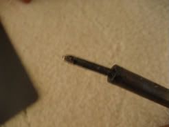
anyway, my issue probably comes from the iron and solder I'm using :

a cheap (8€) 40W iron, not adjustable and 1mm solder 60/40

I m probably going to try ordering this : MET@SHOP

the tip is 0.6*0.8mm and I think it s a hakko clone, so should be good stuff. Or I ll get a 15W weller

and if I still cant solder properly with this thing, well I ll resort to buying the ad8610 premounted

once more, thanks a lot for your help and your advices tangent
 
Sep 30, 2008 at 6:47 PM Post #430 of 1,084
Also get some thinner 63/37 solder. It will be easier to work with.
 
Sep 30, 2008 at 9:24 PM Post #431 of 1,084
I used nothing but this baby for my mini3, and it was easy enough doing the soic-8 pin-by-pin. A little slower, but for me, it was easier than the drag-soldering method(probably cause I didn't use flux).


IMG_0778.jpg


If all else fails.. you could pre-tin the pads, and heat up and press down on each of the legs..(this is probably really bad advice though, since there is no flux on the opamp legs. )
 
Oct 3, 2008 at 4:25 AM Post #434 of 1,084
I just completed installing all of the parts on a PPAv2 board. The board looks pretty good to me, no messy joints, etc. I cleaned it up and connected it to my tread that I built a few days ago. When the amp is powered on I get a very hot left channel with the other two are not getting warm at all. It seems to be just the two output transistors and perhaps the resistor that is getting warm. I'll post some pictures tomorrow but does anyone have any ideas on where to start? I have searched quite a bit and read all of the documentation I can find. When I test from OG to OL I see about 500mv and from OG to OR I see 3.5mv.
 
Oct 3, 2008 at 3:58 PM Post #435 of 1,084
I poked around some on the board this morning. With the op amps out I see 20v on each op amp socket which is inline with what I am sending to it. With the op amps in the sockets I see 9.5v at each op amp. I measured the current draw in this scenario and I see about 9.8ma of current at the V+ terminal when the op amps are installed and the left output transistors getting hot. Any ideas of where I should look next?

BTW please excuse the 100k in positions R6L and R6R. I have some 470Ks on order but they are not here yet.

http://img114.imageshack.us/my.php?i...f001541np8.jpg

http://img114.imageshack.us/my.php?i...f001542iu2.jpg
 

Users who are viewing this thread

Back
Top