My DIY electrostatic headphones
Feb 28, 2021 at 3:55 AM Post #3,751 of 4,059
do you have the parts list and a pcb ?
well it is there, right beside the schematics:
https://nectarsound.net/diy-amplifier/

but I agree with @chinsettawong : with approximately the same effort and part cost you could build one of Kelvin Gilmore's solid state amplifier designs.

I did that also with a heavily modified output stage, and nowadays available parts, reduced idle current (5mA is just enough), and of course I designed the PCB for myself because that is the funniest of the whole process. Needless to say: I'm happy with the result.

On the other hand, no matter what you build first, it is likely that you will build at least one more to be even better.

My kids were asked me to build one for them also, so I already started to design my next one.
 
Mar 5, 2021 at 10:22 AM Post #3,754 of 4,059
@tib8
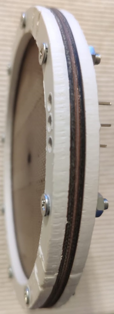
The )( shape is important for me for 2 reasons - 1st to make the stator sturdy, so it does not vibrate on electrostatic forces. (for my normal designs I use double sided 1mm FR4. 2-nd to "follow" the shape of the membranes (when +-360V is applied to them they bend against each other. With a flat stator the center of the membranes is closer to the stator. By the way, this also applies to the classic 2 stator design, because membrane is always attracted more to one of the stators. The option of ordering PCB is good, I have considered it many times, but this is going to be a pretty complicated board. And before I do that, I want to check if it's worth it :relaxed: - for CNC this is pretty simple job. I made already 4 FR4 0.6 mm stators for about 1 hour including the about 2000 holes.
Soldering in the middle is a bit of a challenge, I need to solder inside a 1mm hole a thin layer (35um) of copper.
Unfortunately I can't give you advise on improvement of the stretching, because I use the same wet "glass table" method. I stretch the membrane with a microfiber cloth to remove any wrinkles. Then as you do I just drop the frames and press for about half an hour with something flat and heavy. Your results are quite similar to what I measure with mine - about 140-160 Hz, +-360V and 0.6mm spacing. If I go higher they become unstable. Still I got pretty good bass measured down to 10-15 Hz. Once I got 5Hz, but with a DC amp (no decoupling capacitors) and membranes were unstable. By the way I measured many times the FR response and I think tension does not affect the bass so much as the sealing of the earpads.
Since I do this stretching once in a year or when I make a new model, I don't have much data to share. I believe tire jig is the answer, I just have to make one and do some experiments with different tensions and measurements. But the frames I have are only the ones I use in the phones and I'm too lazy to cut many of them to compare.
The sound level is also good for my taste, but it's far from a dynamic headphones. So if I want to listen very loud, the amp starts clipping.
One more question: if you achieve this )( shape, then are you going to completely ommit the spacer beside the membrane and feed the bias by the outer edge of the stators? Or spacers are still needed?
 
Mar 5, 2021 at 1:08 PM Post #3,755 of 4,059
One more question: if you achieve this )( shape, then are you going to completely ommit the spacer beside the membrane and feed the bias by the outer edge of the stators? Or spacers are still needed?
I actually already did the dual stator assembly - soldering in the middle was not difficult at all. I hope the copper will not peel off, but I doubt it, because the spring force is really very small.
I don't think I can omit the spacers, this means the membrane will be moving almost just in the middle. The spacer between stators is just 0.5mm and looking at them you can't even notice they are bended. On the other hand I have to have some contact for the bias for the membranes. Gluing them to an outer copper plate might not give a reliable electrical contact and most important - I always want the coating to face the stators to avoid humidity influence. Unfortunately I ran out of 0.5 mm FR4, so my spacers will be 0.65. This makes 0.65 +0.5 +0.25 = 1.4mm distance in the middle and 1.15 at the edges. I guess I will have to increase the bias to +-1kV so they sound loud. Since my isolation is FR4, which has 4 times (if I remember correctly) higher dielectric constant than air, it may improve things a bit.
WhatsApp Image 2021-03-05 at 19.51.12 (1).jpeg
WhatsApp Image 2021-03-05 at 19.51.12 (2).jpeg
WhatsApp Image 2021-03-05 at 19.51.12 (3).jpeg
WhatsApp Image 2021-03-05 at 19.51.12.jpeg
 
Mar 6, 2021 at 5:58 AM Post #3,757 of 4,059
Very nice looking driver. What is the hole size?
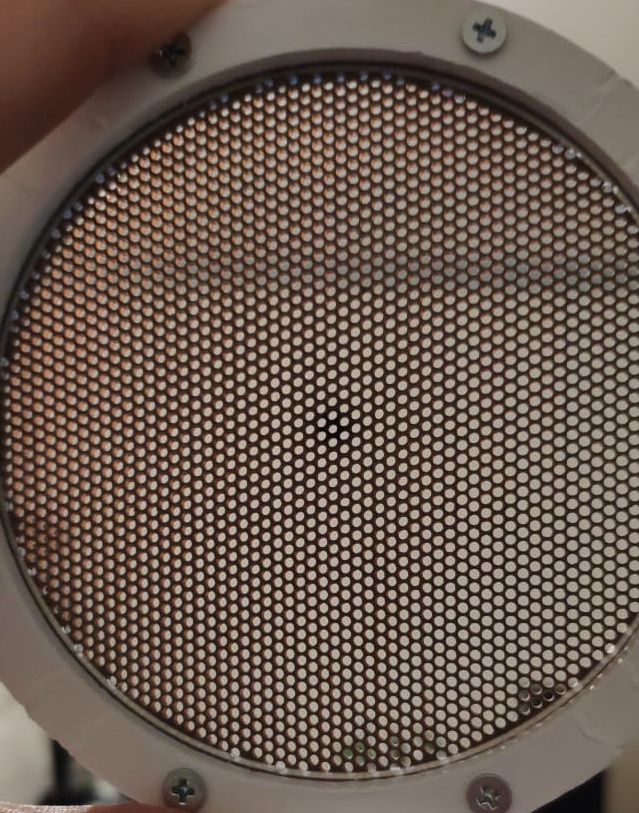
Thanks, holes are 1.2mm area is 88mm., 1.625 distance between and pattern is 60 deg. I made a mistake in my previous post, the holes are 2677, 49.5% open area. I used as mentioned before 2 single sided 0.6 mm FR4, separated at edges with 0.6mm ring and soldered in the 6 middle holes. I was skeptical, but this shape gave surprisingly good sturdiness. I can't compare it with 1mm double sided stator, because the holes there were 1.8mm and open area was about 30%, but by finger it feels the same. Otherwise a single stator drilled like this is very soft and bends in all directions.
 
Last edited:
Mar 8, 2021 at 7:10 AM Post #3,758 of 4,059
I actually already did the dual stator assembly - soldering in the middle was not difficult at all. I hope the copper will not peel off, but I doubt it, because the spring force is really very small.
I don't think I can omit the spacers, this means the membrane will be moving almost just in the middle. The spacer between stators is just 0.5mm and looking at them you can't even notice they are bended. On the other hand I have to have some contact for the bias for the membranes. Gluing them to an outer copper plate might not give a reliable electrical contact and most important - I always want the coating to face the stators to avoid humidity influence. Unfortunately I ran out of 0.5 mm FR4, so my spacers will be 0.65. This makes 0.65 +0.5 +0.25 = 1.4mm distance in the middle and 1.15 at the edges. I guess I will have to increase the bias to +-1kV so they sound loud. Since my isolation is FR4, which has 4 times (if I remember correctly) higher dielectric constant than air, it may improve things a bit.
Looks incredibly good!
Is this the complete driver with membranes or the stator only?
If the finished driver, does it fulfills your expectations?
 
Mar 8, 2021 at 2:06 PM Post #3,759 of 4,059
@tib8
Thanks, you're being nice - :relaxed: .The frames look terrible, because I made them from a plumber pipe cap, but for now it's just for testing. Later I will redo with either wood or some good looking plastic. Yes this is the final assembly without the membranes, earpads and connectors. And only one channel, can't find the time to do the second and glue the membranes. And testing with one channel makes sense for the FR only, maybe it's just me, but if I don't have both cups on my ears, I cannot evaluate the sound quality.
 
Mar 14, 2021 at 4:49 AM Post #3,760 of 4,059
Finally assembled the new design. )( shaped stator, single sided, copper inside, 88mm active area, 50%, 1.2 mm holes. 0.65mm spacers. First impressions compared to 100/70 ovals (60cm2 vs 55cm2):
1. A bit deeper bass - at first I was disappointed - I expected more, but then I realized that extending an FR lower with few Hz, which is already 15 Hz would not make much difference in hearing. Highs sound a bit better, middles are a bit lower. Overall sound is a bit softer - which I already noticed as a difference between circle and oval designs.
2. Surprisingly loud - (as mentioned in previous message the distance membrane - copper at edge is 1.15mm and in the middle is 1.4. (with the oval spacers are 0.6mm). I thought it would be much less loud with the same amp and bias, but it's actually almost the same. Two things only come to mind - the big dielectric constant of FR isolation and bit bigger area.
Overall I'm very happy so far - not much improvement over the same (almost) size ovals, which already sound great, so this was to be expected I'm very keen to put some headband, and measure them, once I find some time for it.


ESH 88 circle.jpeg
 
Last edited:
Mar 15, 2021 at 6:54 AM Post #3,761 of 4,059
Finally assembled the new design. )( shaped stator, single sided, copper inside, 88mm active area, 50%, 1.2 mm holes. 0.65mm spacers. First impressions compared to 100/70 ovals (60cm2 vs 55cm2):
1. A bit deeper bass - at first I was disappointed - I expected more, but then I realized that extending an FR lower with few Hz, which is already 15 Hz would not make much difference in hearing. Highs sound a bit better, middles are a bit lower. Overall sound is a bit softer - which I already noticed as a difference between circle and oval designs.
2. Surprisingly loud - (as mentioned in previous message the distance membrane - copper at edge is 1.15mm and in the middle is 1.4. (with the oval spacers are 0.6mm). I thought it would be much less loud with the same amp and bias, but it's actually almost the same. Two things only come to mind - the big dielectric constant of FR isolation and bit bigger area.
Overall I'm very happy so far - not much improvement over the same (almost) size ovals, which already sound great, so this was to be expected I'm very keen to put some headband, and measure them, once I find some time for it.
You are right about the dielectric constant. The epsilon relative of FR4 is about 4.3, which means that 4.3 times less voltage drops on it than on air (if we imagine two serially connected capacitors). So FR4 seems 4.3 times thinner than it is in reality. So your equivalent air-gap is 0.65+0.5/4.3=0.766mm. Which is only 1.27 times of your normal 0.6mm, that means only 20*log(1.27)=2dB loss in loudness.
If that would be the price of the stable membranes the it definitely worths it. 👍
 
Mar 15, 2021 at 1:30 PM Post #3,762 of 4,059
You are right about the dielectric constant. The epsilon relative of FR4 is about 4.3, which means that 4.3 times less voltage drops on it than on air (if we imagine two serially connected capacitors). So FR4 seems 4.3 times thinner than it is in reality. So your equivalent air-gap is 0.65+0.5/4.3=0.766mm. Which is only 1.27 times of your normal 0.6mm, that means only 20*log(1.27)=2dB loss in loudness.
If that would be the price of the stable membranes the it definitely worths it. 👍
Thanks for the calculations! I was thinking of it on another way - F=Q1.Q2.k/d^2. Which means with k = 4 times higher, F would be 4 times higher. and since the distance is about 2 times higher it becomes almost the same, but here the force is actually a sum (??) of 2 forces - within air and within FR4, and this I didn't know how to express. On the other hand the transparency is higher, meaning there is less copper area for the electrostatic field. It took me about 5 mins to give up on formulas, so I guess your method is better. Anyway, it's definitely far more stable (also because of the )( shape) and I think I can safely increase the bias twice, which will give me much more loudness, than I can get with the ovals.
 
Last edited:
Mar 15, 2021 at 7:27 PM Post #3,763 of 4,059
Thanks for the calculations! I was thinking of it on another way - F=Q1.Q2.k/d^2. Which means with k = 4 times higher, F would be 4 times higher. and since the distance is about 2 times higher it becomes almost the same, but here the force is actually a sum (??) of 2 forces - within air and within FR4, and this I didn't know how to express. On the other hand the transparency is higher, meaning there is less copper area for the electrostatic field. It took me about 5 mins to give up on formulas, so I guess your method is better. Anyway, it's definitely far more stable (also because of the )( shape) and I think I can safely increase the bias twice, which will give me much more loudness, than I can get with the ovals.
I imagine the voltage drop across your driver like this:

1615847548182.png


Since most of the voltage still drops in the air you should be careful with increasing the bias voltage. Do NOT go anywhere near to the 2kV/mm.
I would use only 1.25 .. 1.5 times higher bias voltage only to cover that extra voltage drop in the FR4, which would not happen if the Cu would be on the outer side of it.

About the decreased (50%) useful area:
F = Eair * Q
F = m * a
C = Q / U
C = A * epsilon / d
=> a = E * Q / m = E * U * C / m
Where the 'm' is the mass of the membrane (+ the air around it) and 'a' is the maximal acceleration of the membrane if a given Q is applied (due to a given U).
If the useful area is smaller, that decreases the C (so decreases Q too), while the mass of the membrane is the same, but due to the larger hole area, the air could be moved a bit more easily, so there is a holpe that visible mass 'm' will be a bit smaller too. The amplifier has to pump less Q in each period - it sees smaller capacitive load, so will be able to extend its high freq range.
From the combination of these factors it is hard to predict which will be dominant, but they will likely affect the high frequency response of the driver...
It would be interesting to experiment with identical drivers, which differ onlyin useful area, and measure their freq response... and test the stage imaging, separation, etc, which can not be measured...
 
Mar 16, 2021 at 5:11 PM Post #3,764 of 4,059
Well I forgot to mention also that the area is higher than the ovals, so it becomes complicated. Otherwise I agree, it would be nice to experiment with identical drivers varying one by one different components. I guess this is done by the manufacturers, but who of us can afford it? Who has time to drill 10 different ratio stators? There are too many factors playing roles here. For example after listening for about 3 hours with the new drivers and swapping them from time to time with the ovals, I found some things that I didn't like so much. Bass is extremely powerful and on some songs masks the middles and highs. The cable is almost twice longer than with the ovals and because my amp is not very powerful it struggles with the increased capacitance, hence the highs are muffled. Once the phones get warmer from my head, the membrane tension decreases a bit and bass becomes even more. I love bass, but this is too much. I guess this can be fixed with increased tension and shorter cable. So my first impressions were wrong. Bass is too much, and highs sound weaker. I really need to do FR to see how it looks compare to the ovals.
I wouldn't go nowhere near even 1kV per 1mm, my bias is now around +-350, and I intend to double it at most. So I will have max 700v/mm compare to the 580V /0.5mm in the classic design.
 
Last edited:
Mar 18, 2021 at 4:34 PM Post #3,765 of 4,059
I made some FR at last. Circle has about 10 dB (voltage on the mic) difference from 20-1000Hz, but it drops quickly down from 50-300 and then it's almost flat. Ellipse follows almost the same, but with just about 3dB drop. I guess this is the reason circle sounds so "bassy" and soft. From 1k-30kHz both are pretty similar and surprisingly both go up with 10dB at 30k. I don't know if this is real, because my mic is not good for a real FR measurements. The curves look very similar with all designs. For example I always see a bump between 20 and 100 hz, then almost flat, then some peak drops at 600 and 1000 and a slow but constant increase from 1k to 30k. I can only compare values at different frequencies with different phones.
 

Users who are viewing this thread

Back
Top