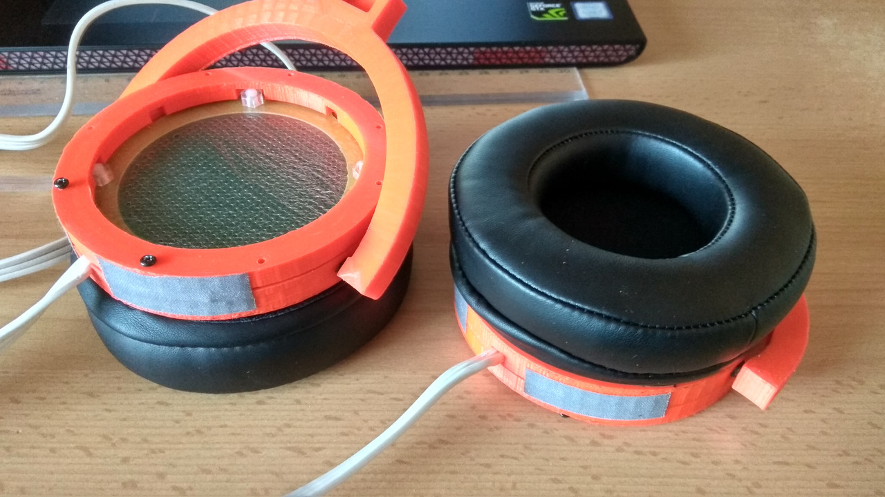
My DIY electrostatic headphones
Apr 15, 2018 at 1:40 PM Post #2,926 of 4,059
I still have problems with acquiring 0.5mm thickness FR4 for spacers. I think I can source here stainless steel and have it laser cut. I'll use FR4 with 1.5mm thickness for the stators. Because of stainless steel is also a conductor, I'll make the cut the inside ring slightly bigger than the active area of the stators. Would that be okay?

Why not use a non-conductor? You can get Mylar/Melinex in thicker sheet and I think it will laser cut, although it would probably be cheaper to talk to a company that does click-cutting and have a steel-rule tool made. I'd be surprised if you couldn't find someone to make you the tool for less than 100$ and the production process is really cheap. My diaphragm area is quite big and I don't know whether 0.5mm will be OK, so I'm going this way for insulators and having them made in a thin grade which I can stack to determine a safe working clearance.

Ed Form
 
Apr 15, 2018 at 6:10 PM Post #2,927 of 4,059
As promised we made a guide on how to build your electrostatic headphones without needing to read close to 200 pages of forum posts.
You can find our very first version here: https://github.com/Azrael3000/headphone-guide or read the pdf directly: https://github.com/Azrael3000/headphone-guide/raw/master/guide.pdf

This work is under a CC license, so everybody can copy, modify and redistribute this document (with some minor constraints). If you have comments on how to improve it feel free to let us know either on the dedicated forum thread: https://www.head-fi.org/threads/electrostatic-headphone-construction-guide.877412/ or on Github.

Cheers,
Arno
 
Apr 16, 2018 at 12:00 PM Post #2,929 of 4,059
I still have problems with acquiring 0.5mm thickness FR4 for spacers. I think I can source here stainless steel and have it laser cut. I'll use FR4 with 1.5mm thickness for the stators. Because of stainless steel is also a conductor, I'll make the cut the inside ring slightly bigger than the active area of the stators. Would that be okay? Here's my design as of the moment for the spacers and stators.


Your design looks nice. But if I were you, I would use FR4 for both stators and spacers. I don't see any advantage of using either stainless steel or aluminium. The FR4 of the right thickness isn't that difficult to source. Let me know if you really can't find them.
 
Apr 16, 2018 at 6:13 PM Post #2,930 of 4,059
They are koss extension cables. $20+shipping from koss, but you can only order them by calling their customer service number. I cut off the ends and molded a stax plug from a cast I made of the plug from my stax headphones.

Hi bui501-tech, thank you for your information.

It was over half a year ago, they refused to sell it again… When I called them again, they accepted the order this time. ???
I was planning to cut and use my 5m original STAX extension cable.
 
Apr 16, 2018 at 6:39 PM Post #2,931 of 4,059
Hi Inuponken,

Are you using those clips as weights? I don't think you have enough tension there. I once tried water bottles weighing around 0.75 KG each and the tension was still not enough.

Your wooden frame and ear pads look really nice. Wow!

Have you put them together and played some music yet?

Wachara C.

Hi Chisettawong,

I have to re-build the front plates to attach the ear pad and it took time to reorder new material.

About the tension,
This is my method that after repeating trial and error.
Please take my method just for reference…:ghost:

1. Add tension just enough to disappear large wrinkles on the 3um mylar film.
I do not use weights, only added small clips as the previous photos.

2. After the adhesive (contact cement) has dried, apply heat to the mylar with a 1875W hairdryer.
Continue to heat until the small wrinkles are not come back after cooling.
It is necessary to heat for quite a long time (total >10min.) otherwise wrinkles will come back again after cooling.
While heating, the hair dryer becomes too hot and the thermostat turns off many times…

I used the same method to my Omega clone, 2 set of JF clone and modified JF clone but they are very stable.
 
Apr 17, 2018 at 12:20 AM Post #2,932 of 4,059
Hi Inuponken,

Wow, having to apply heat from the hair dryer for that long isn't fun. By the way, what spacer thickness are you using?

I use an industrial heat gun for heat treatment if I need to. It's much hotter. You can't blow it on a single spot for more than a second or two. Otherwise, it'll burn through the diaphragm.
 
Apr 18, 2018 at 2:24 PM Post #2,933 of 4,059
Hi Inuponken,

Wow, having to apply heat from the hair dryer for that long isn't fun. By the way, what spacer thickness are you using?

I use an industrial heat gun for heat treatment if I need to. It's much hotter. You can't blow it on a single spot for more than a second or two. Otherwise, it'll burn through the diaphragm.


0.5 mm.
When the bias voltage becomes 380 V or more, the diaphragm sticks to the stator. I am adjusting the tension now.
The first impression of listening at the bias voltage of 350 V is, there is more presence than my omega clone.
 
Apr 18, 2018 at 8:31 PM Post #2,934 of 4,059
IMG_9603.JPG
IMG_9604.JPG
 
Apr 20, 2018 at 12:54 PM Post #2,936 of 4,059
I gave up 0.5 mm… I tried strengthening the tension until the PCB bends, but still sticking to the stator at 450 - 500 V. I ordered 0.1 mm sheets to make shims and try to make it with 0.6 mm space. Probably I can increase the bias voltage to 600 V with the same tension.

I’m listening with 0.8 mm spacers now and there is no problem even if the bias voltage is increased to 800 V.
Wider spacing reduces efficiency but no problem with my DIY-T2 and KGSS Carbon.
It is very wide range sound! I like it very much!!!
 
Last edited:
Apr 20, 2018 at 1:17 PM Post #2,937 of 4,059
Well, you just haven't found its sweet spot yet.

I know it's not very easy, but it certainly achievable. :ksc75smile:

Oh, by the way, the wood housing might bend a little because of the humidity. So when you screw the front baffle onto the wood, you don't want to screw it in too tight.
 
Apr 21, 2018 at 12:01 AM Post #2,939 of 4,059
The performance of stators is a wonderfully complex field with boundaries imposed on transmission by thickness of the plates, percentage of open area though the plates, and distance between the holes These three boundary parameters interact to generate

1. Resonances analogous to the transmission variations in a Fabry–Pérot optical interferometer, improved by decreasing the spacing between the diaphragm and the stator - which has severe limits, obviously.

2. Exaggeration [spreading] of the resonant effects by coupling between the air-masses of the closely spaced tubes and by interaction between the hole-end effects on inner and outer stator surfaces, improved by moving the holes apart - but then no sound gets through, and by making the plates thin - but thin enough means the plates cannot support themselves, which is bad, and become self-resonant, which is bad also.

3. Diffraction effects, where sound from each element of area traveling outwards through a directly facing hole is interfered with by sound that has travelled from the same element via the holes surrounding the primary hole and arrives with slight delays and subtracts or adds to the output of the main hole depending on frequency - It's a complex two dimensional comb-filter system and messes with the HF end.

The best-case combination of all these parameters is actually a very thin plate with a large proportion of open area generated by very large numbers of small holes that are very close to each other - screen-printing wire mesh is absolutely ideal acoustically but it has no mechanical strength. The mechanical issue of fixing such a stator in space is a problem that has been addressed in the Hifiman Shangri-La [actually it's quite a crude version of the mesh], so it can be done. The standard argument about lots of holes diminishing field strength is a red-herring with fine wire mesh - look at the protective guards round ultra-HV test facilities, the artificial lightning doesn't get through even though the mesh is high open area.

So, to focus on your idea, thin aluminium plates are a valid way to go - thin is good - but keeping them flat is an issue - it's dealt with in the Stax SR009 by bonding the thin plates to a thick but substantially open spider of the same metal, and is one approach I'm taking - incidentally, I'm amused by a number of 009-style designs in this forum that omit holes where the 009 has ribs - the ribs aren't there to block holes, they're there to reinforce the plates; in plates that do not need to be reinforced the rib positions should be filled with holes!! The possibility that the blank areas are used to control diaphragm resonances, which some may have thought, is certainly not true in the case of the 009 where the spider layout is symmetrical and would tend to favour some higher order resonances if such a mechanism were at work.

Ed Form

I am curious to know what is the difference of thickness between these stators... Any guess? :L3000:

8336E123-F71F-4BCE-A2BF-92FD668D8D3B.png


41927A16-783F-4183-9619-9CAAD72CE8ED.png


094A815C-2473-428B-8BEA-2C673B9E5494.png


09509EF6-7626-433D-ACB4-7EECA0B5C833.jpeg
 

Attachments

  • 23B8E821-80D7-43F2-A086-4E60C483D4D4.png
    23B8E821-80D7-43F2-A086-4E60C483D4D4.png
    8 MB · Views: 0
  • B8E74C0E-F664-478A-9025-C4EE3D5AC777.png
    B8E74C0E-F664-478A-9025-C4EE3D5AC777.png
    7 MB · Views: 0

Users who are viewing this thread

Back
Top