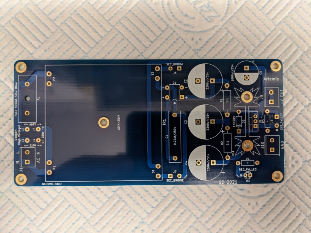
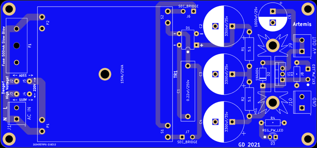
@pmillett : It seems that the dimension of the upper left hole in the PCB drawing is wrong (it's 2,8125 right now, bigger than the PCB itself).
The assembly guide also mentiones that I could find the DXF file of the PCB on your website, but I wasn't able to find it (Wanted to use it to design a 3D printed case).
Thank you for the hard work!


")