Quote:
Originally Posted by plibber
I've swapped out the caps and had a quick listen to make sure that everything works. I'll have to have a long listening session tonight and see how things have changed.
Amperex NOS tubes with the beautiful gold and blue Panasonic caps in place.
|
Looking good! Give those caps a good few days to fully form, the sound should progressively open out over a period of a week or two
Another little thing you may want to try is removing the four 6.3V 220uF non polar output caps and replace them with two 1000uF non polar caps.
No output cap is best, one per channel is second best but two per channel is just horrendous IMO. The only reason they have fitted 4 x 220uF is "size" so they'll fit underneath the board which accommodates the pot and headphone socket, anything larger and they wouldn't fit (unless you lay the cap on its side
) You'll notice that the two 220uF output caps per channel are paralleled making a combined value of 440uF per channel..... after much testing with the WNA amp 1000uF was deemed the best value for the output cap and the same seems the case with the V3.
Whip those 4 x 220uF output caps out and replace with 2 x 1000uF non polars (I used 16V 1000uF) for better bass definition and a degree more clarity. You can just solder over the pads on the spare space for the other two caps or you can fit something like a polypropylene film cap which will bypass the non polar electrolytic output caps.
It's early days and there are quite a few possibilities at the output (no output caps at all for example) but for the time being two 1000uF non polar output caps and a couple of polyprop film caps sounds marginally better than it does with 2 x 220uF NP caps per channel. I haven't even got around to measuring the DC offset without the output caps in place yet.... if it's low enough then it's possible they can be removed and the pads jumpered together....... it's also feasible (enough room on the board) to parallel together a bank of film caps but I doubt the end result would be worth all the bother...... maybe just a 1000uF non polar per channel with a 4u7 polyprop in parallel would be the cheapest and best overall solution.
Anyways, it's well worth trying! All you need to buy are a couple of 1000uF non polar 16V caps (about 30p each) and see what you think.
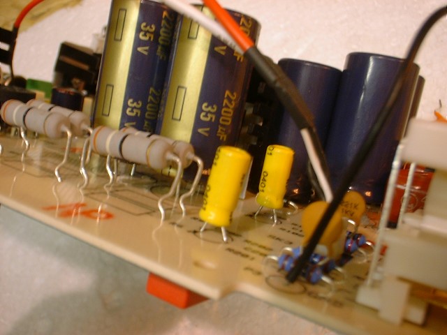
Here are a few pics:
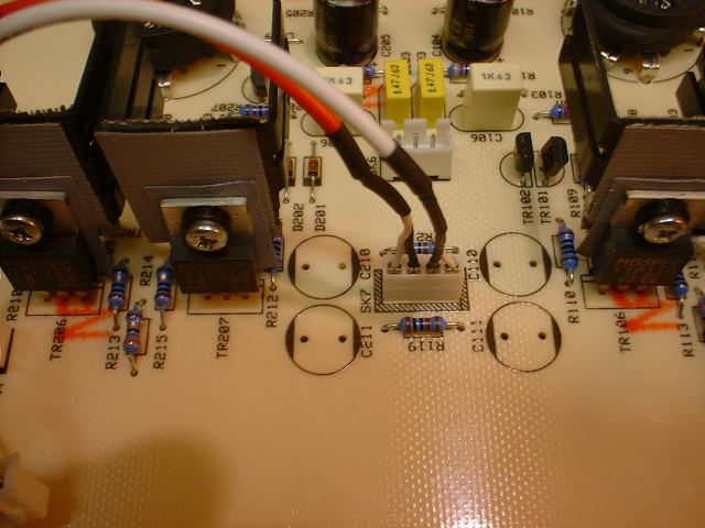
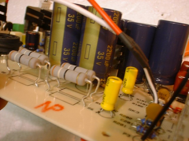
Remove the 4 x 220uF non polar output caps
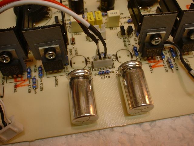
Solder two 1000uF non polar caps in their place.... this leaves two spare spaces for caps which can either be left blank or used to house a couple of film bypass caps
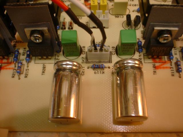
spare capacitor holes shown.... either solder over them or fit bypass caps or another couple of 1000uF caps or whatever takes your fancy!
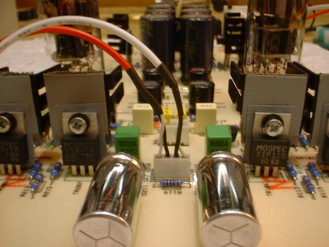
I've temporarily fitted a couple of polypropylene caps into the spare cap bays which are acting as bypass caps for the non polar output caps.
Lots more to come soon........