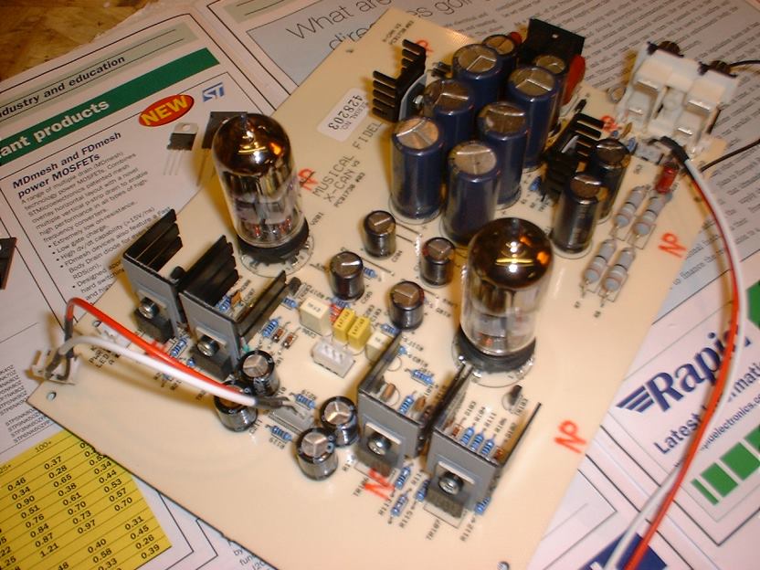
MF X-Can V3 in the house :-)
Oct 31, 2005 at 12:06 PM Post #16 of 73
Quote:

Originally Posted by Sugano-san
But doesn't it need a different PSU? The V2 needed 12VAC, whereeas the V3 needs 24VAC, IIRC. Agree? Couldn't that imply that some of the basic characteristics of the circuit may have changed, too?


Yes, the V3 PSU is 24VAC but it's 12 - 0 - 12Volts AC 500mA.

V3adaptor.gif
 
Nov 1, 2005 at 10:04 PM Post #17 of 73
Quote:

Originally Posted by mysticaldodo

The thing worked fine actually for a few months. I only added the customer made PSU last month so maybe thats the culprit? To be honest, I don't think it ran any warmer compared to the Walmart supply. Anyway its mom's fault. She turned off the fan and for some reason pile a big stack of TIMES mag on the XCan while its still warming up in wholesome tropical weather. I've let it run for a week with the fan turned on with the cap upgrades and there was no problem.


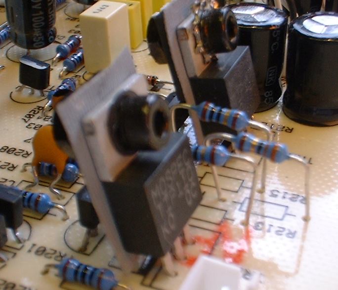
How's it going, have you had it repaired yet? I had a look inside mine and noticed that the resistors next to the transistors have been fitted so they are high up off the board with lots of leg showing
confused.gif


I can only assume this is some kind of "in service" cheap fix to cool things around that area down a bit.... either that or the person who populated the PCB was drunk:

DSCF0018.jpg


I don't know what caused your transistors to go into meltdown but I sure as hell am going to fit some heatsinks onto mine and fit the resistors properly onto the PCB. I've ordered some TO220 heatsinks, some TO220 insulating bushes and some TO3P adhesive coated thermal pads so that should help dissipate the heat (pics to follow).

Also decided to remove those Jamicon caps and fit some good quality, low ESR, Panasonic FC caps bypassed with WIMA polypropylene film caps... this made a HUGE improvement to the V2 so hopefully it'll really max out the V3 also
smily_headphones1.gif
Basically, if there's an electrolytic.... bypass it with a small polypropylene..... the X-can series responds very well to tweaks in the capacitance department.

The philips 6922 valves have been replaced with a couple of 6N23P-EV's from my stash of NOS russian valves and whooooah! what an improvement they make too... those philips 6922's are just awful sounding..... fortunately the design of the amp is good and it responds favourably to better quality parts so it's well worth spending a few quid over and above the cost of the amp on decent caps and things.

Will report back once the mods are in place
smily_headphones1.gif
 
Nov 2, 2005 at 3:10 PM Post #18 of 73
Hi mysticaldodo,

I've just spoken with the MF technical guy and the reason they are now fitting the 3 resistors between TR106 & TR107 so high off the PCB is "to protect the PCB in case of a fault" ie the resistors will burn out but your board will not be blackened / damaged.

I just wonder if they've had a few of these back with scorched boards and as a result have decided to fit the resistors away from the PCB to make repairs easier..... I notice on your board the resistors are flush mounted on the PCB and you can see what a mess the burnt out resistors have made of the board. Fortunately it appears (from your pictures) that the tracks and pads are still intact so it should be easy enough to replace the resistors and transistors with new ones. R213 appears to be 10ohm, R214 is 32ohm and R215 is 10ohm. I'll check out what transistors you need later on when I'm under the hood.

Edit: I flush mounted all 6 of the raised resistors last night..... looks like I'll be raising them off the board again to protect it from scorching in "the event of a fault" hmmmmmm..... the word "fuse" springs to mind.
 
Nov 2, 2005 at 7:10 PM Post #19 of 73
Quote:

Originally Posted by PinkFloyd
....The philips 6922 valves have been replaced with a couple of 6N23P-EV's from my stash of NOS russian valves...


I ordered a pair from your source. Hopefully they get shipped today
cool.gif
In looking for a source for these valves it appears that there is recent spike in demand for them. In fact, I ended up paying $16 each (about 3 times what you got them for). Get them while you still can
tongue.gif
Fortunately at this price they are still relatively inexpensive and a bargain if they sound anything like Mullards.
 
Nov 3, 2005 at 2:07 AM Post #20 of 73
it would seem as though they may have seen a few.

I used to own a full MF F series set up and i must say i was impressed with the sound but not the support.
biggrin.gif
biggrin.gif
 
Nov 3, 2005 at 12:41 PM Post #21 of 73
Quote:

Originally Posted by troublemaker
i was impressed with the sound but not the support.
biggrin.gif
biggrin.gif


Well, I'll never know what their support is like as I've just invalidated my warranty by fitting Panasonic FC caps (bypassed with polyprops) new valves, heatsinks and a few other bits and bobs....... I'll be adding more bypass caps (silvered mica etc.) to attain a broad area of low impedance but, so far, the polyprops are in position. I'll probably also replace all of the resistors with 0.1% 15ppm temp coeff types...... one thing's for sure...... bang goes my "warranty"
evil_smiley.gif


DSCF0007.jpg

Lovely low ESR Panasonic FC's resplendent in their gold and blue livery
tongue.gif


DSCF0014.jpg

Stage one of the bypassing in place

DSCF0025.jpg


DSCF0028.jpg

Heatsinks

DSCF0032.jpg
 
Nov 3, 2005 at 1:45 PM Post #22 of 73
PinkFloyd, your modified V3 looks very impressive!

How does it sound with all your modifications? What differences do you notice?

I'm interested in doing something similar myself for my V3. Would there be a chance that you post your parts list? Also where do you source your components and valves?

Thanks
 
Nov 3, 2005 at 5:19 PM Post #23 of 73
Quote:

Originally Posted by PinkFloyd
I'll do my best just to listen to the amp and enjoy it and to heck with swapping the capacitors just for the sake of it....


heh pinkie, you held out for a little more than a week.
smily_headphones1.gif


fwiw though, do you do bypasses with electrolytics in the signal path only or all electrolytics in general? is this amp have input/output coupled caps?
 
Nov 4, 2005 at 10:58 PM Post #24 of 73
Quote:

Originally Posted by plibber
How does it sound with all your modifications? What differences do you notice?


So far... slightly more dynamic, smoother and more clarity. I removed the bypass caps as fitting just one in parallel with the electrolytics was kind of defeating the object of the exercise..... I should have fitted 3 or 4 bypass caps to each electrolytic to gain a broader area of low impedance...... I'll go under the hood again once I'm armed with an assortment of suitable bypass caps..... just fitting the polyprops in parallel with the electrolytics muddied the sound slightly so, at the moment, the amp is just running with the Panasonic FC low ESR capacitors in position which certainly do sound better than the stock Jamicon caps IMO.

Quote:

Originally Posted by plibber
Would there be a chance that you post your parts list? Also where do you source your components and valves?


Sure! The Panasonic FC capacitors are sourced at RS components here are the part numbers:

2200uF 35V x 6 315-0782
1000uF 35V x 4 315-0754
100uF 63V x 4 315-0962
10uF 50V x 2 315-0805

They only sell in multiples of "5" so you will have to buy 10 of the 2200uF and 5 of each of the others.

All the other stuff I had kicking about so don't have any part numbers to hand but Rapid stocks everything you may need apart from the Panasonic FC caps. When I'm finished messing about with it and if it sounds good I'll post up all the bits and bobs I've used...... basically, for starters, the Pansonic FC low ESR caps make quite a substantial improvement to the sound quality and they are well worth fitting.

The guy I got the russian valves from seems to have disappeared I'll PM you his details if he surfaces again.


Quote:

Originally Posted by adhoc
heh pinkie, you held out for a little more than a week.
smily_headphones1.gif


I know, this is like an illness...... I can't just sit and listen to the music I've always got to prod about with things
blink.gif


Quote:

Originally Posted by adhoc
fwiw though, do you do bypasses with electrolytics in the signal path only or all electrolytics in general?


Generally "all" of them though bypassing with just one cap was not a good idea (resonant circuit) I'm going to parallel 3 or 4 film caps to the electrolytics instead and give that a try.

Quote:

Originally Posted by adhoc
does this amp have input/output coupled caps?


Yes. 10uF input 220uF output (I think)
 
Nov 4, 2005 at 11:42 PM Post #25 of 73
Quote:

Originally Posted by PinkFloyd
...
The guy I got the russian valves from seems to have disappeared I'll PM you his details if he surfaces again...


I got an e-mail from him yesterday. It seems that he is busy trying to fulfill orders for these. He said that he had 100 coming in and 60 were already called for before I placed my order. He also said that he had to pay a premium for this batch (therefore increasing my price by a factor of 3
eek.gif
) I'd be interested to find out if you get any more for the price you paid.
 
Nov 4, 2005 at 11:56 PM Post #26 of 73
Quote:

Originally Posted by Juergen
I'd be interested to find out if you get any more for the price you paid.


I doubt it what with this sudden "surge" in buying, I should have kept my gob shut
plainface.gif
 
Nov 6, 2005 at 2:28 PM Post #29 of 73
Quote:

Originally Posted by plibber
Thanks PinkFloyd! I'll certainly give those a go and see how they sound
icon10.gif


Give them a go I think you may like the sound, it's more open and very airy and "fleet of foot" more dancing like a ballerina than clumping about like a bricklayer...... the bass is much more musical and less ploddy sounding...... remember that the valves also play a part in the overall sound, the stock JAN philips are "ok" but they can really be improved on for not a lot of money.

This is not just swapping out capacitors for the sake of swapping them out.... the reason I chose Panasonic FC is for their HF performance and they are very low ESR "equivalent series resistance" compared with the stock Jamicon 85C general purpose caps.... they really do sound better IMO.
 
Nov 7, 2005 at 6:19 AM Post #30 of 73
Quote:

Originally Posted by PinkFloyd
Hi mysticaldodo,

I've just spoken with the MF technical guy and the reason they are now fitting the 3 resistors between TR106 & TR107 so high off the PCB is "to protect the PCB in case of a fault" ie the resistors will burn out but your board will not be blackened / damaged.

I just wonder if they've had a few of these back with scorched boards and as a result have decided to fit the resistors away from the PCB to make repairs easier..... I notice on your board the resistors are flush mounted on the PCB and you can see what a mess the burnt out resistors have made of the board. Fortunately it appears (from your pictures) that the tracks and pads are still intact so it should be easy enough to replace the resistors and transistors with new ones. R213 appears to be 10ohm, R214 is 32ohm and R215 is 10ohm. I'll check out what transistors you need later on when I'm under the hood.

Edit: I flush mounted all 6 of the raised resistors last night..... looks like I'll be raising them off the board again to protect it from scorching in "the event of a fault" hmmmmmm..... the word "fuse" springs to mind.


Nice to read that
cool.gif
. I haven't send it in for repair yet, its my last week of college and I'll send it in after that.

I never thought about adding heatsinks. Thats something to think about
blink.gif


Its still working, but there's some distortion on one of the channesl. Have to double check
 

Users who are viewing this thread

Back
Top