Little Dot MK VI / Little Dot MK VIII SE Owners Unite
Sep 18, 2015 at 9:41 PM Post #2,161 of 2,724
Hi misterX

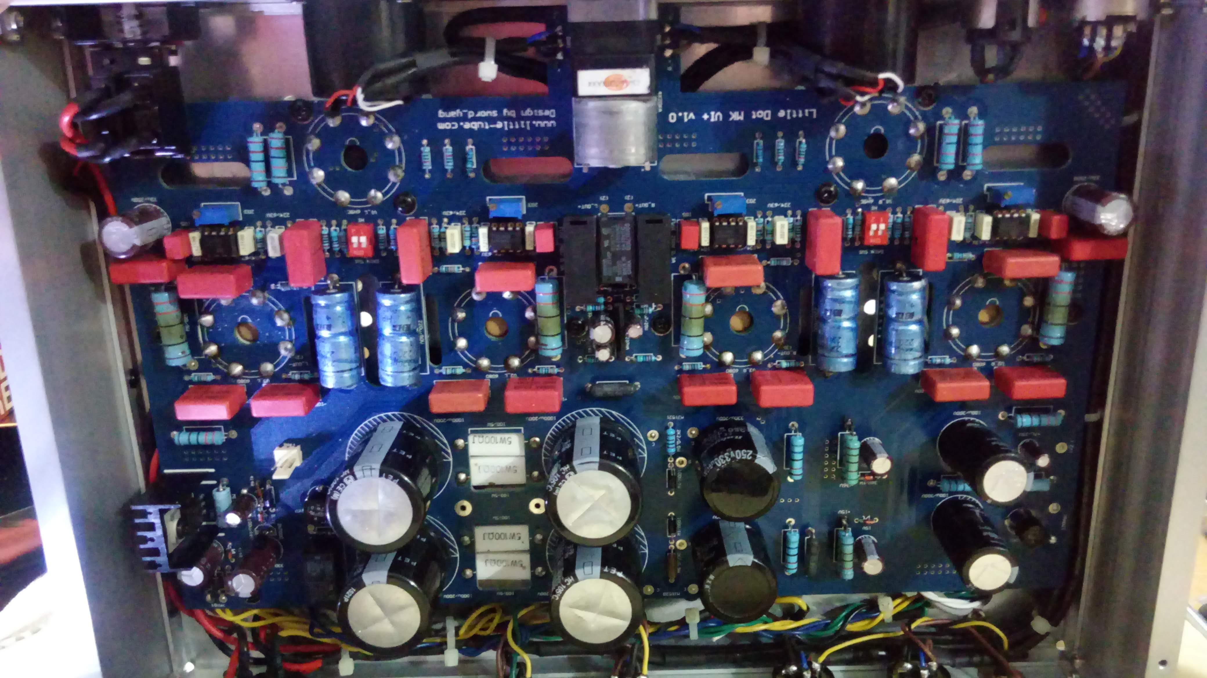
What you say make sense, I need more time to trace the wiring of the meter.
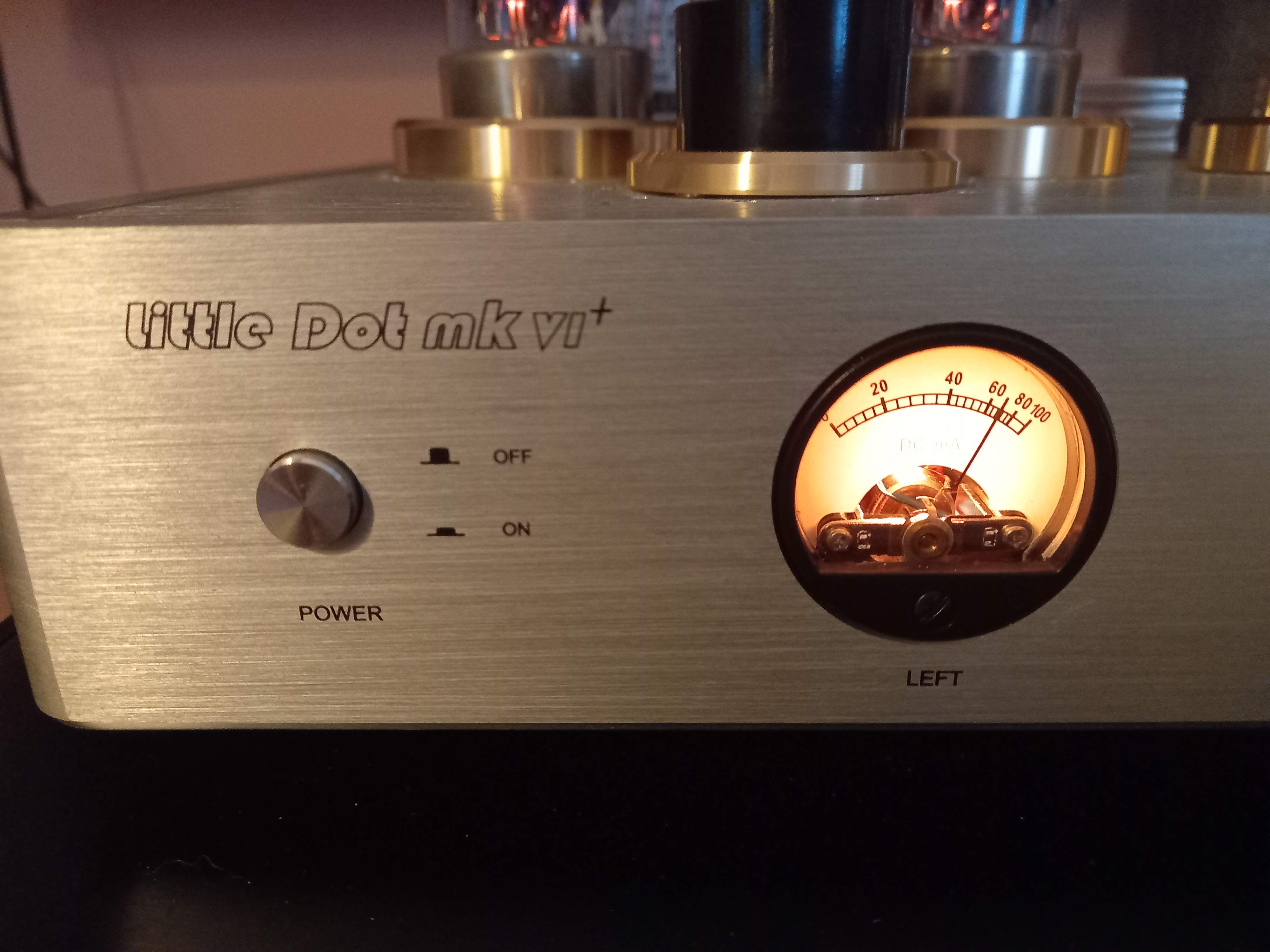
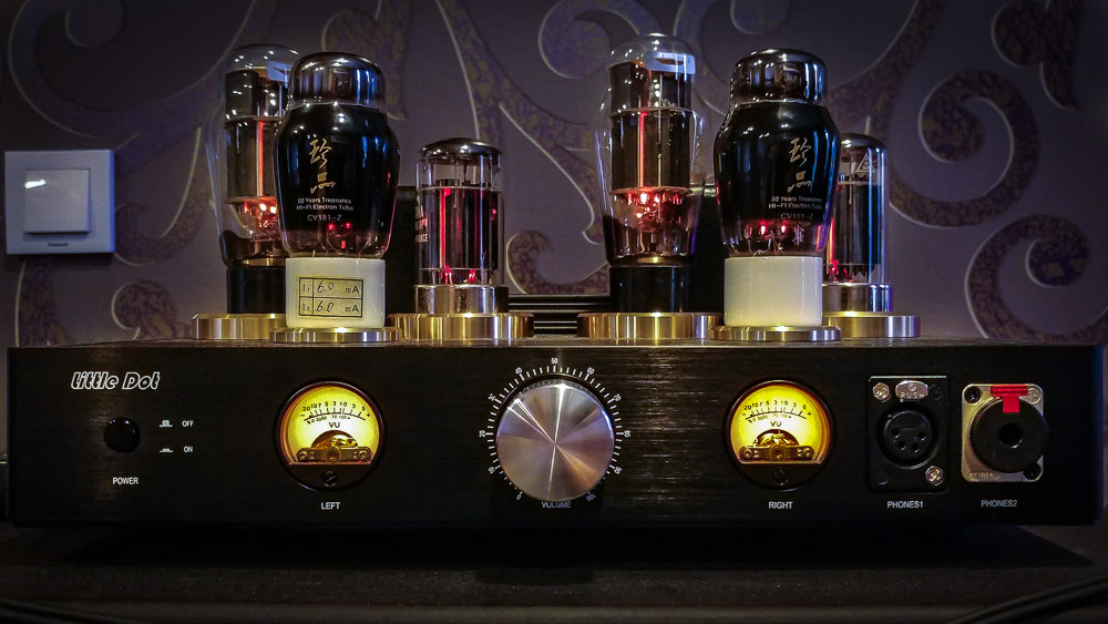
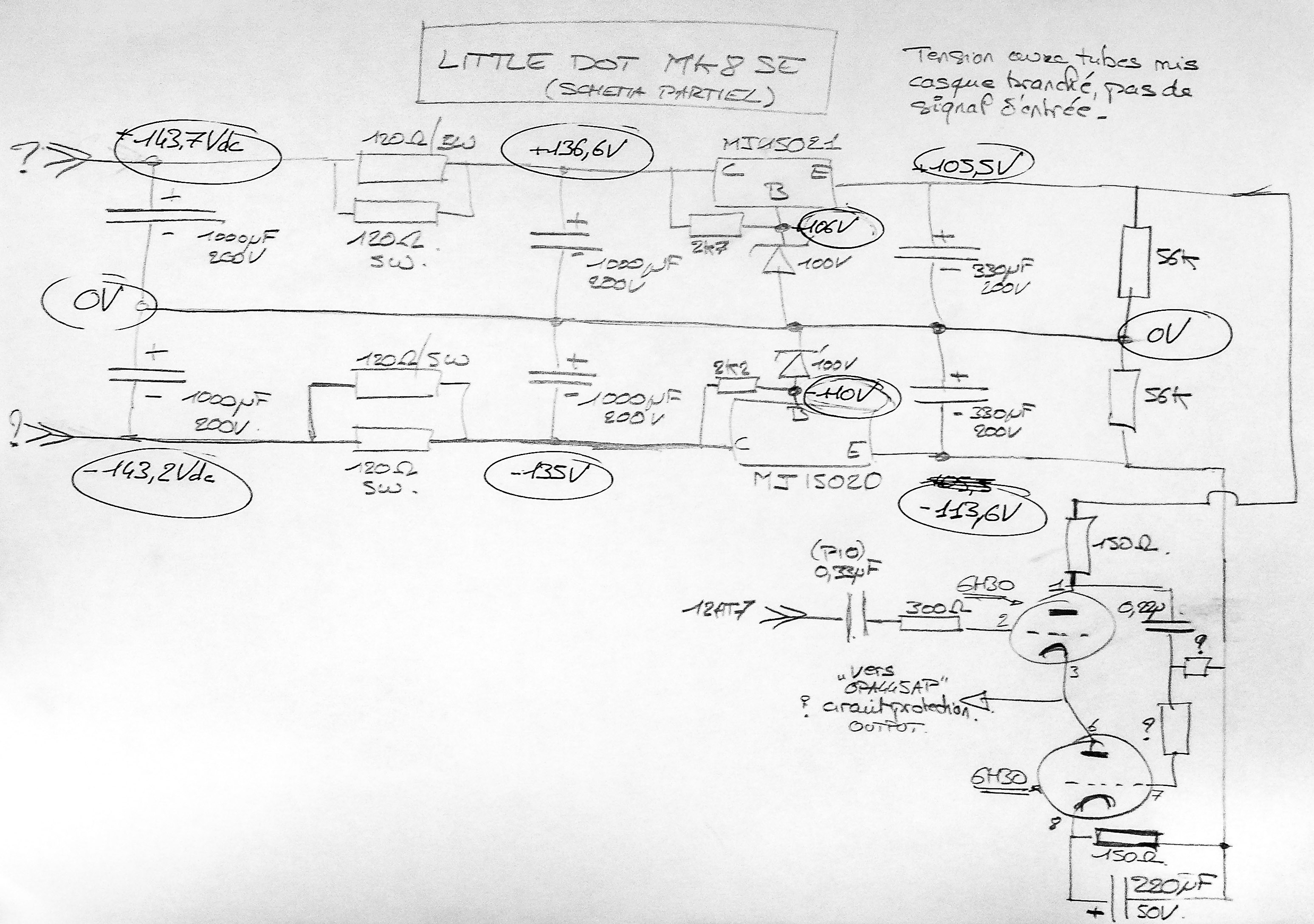
What I am guessing is that the auto biasing circuitry will maintain the current flow to be identical to go into the two power tubes, and the meter is to monitor the +ve signal tube (which should then be identical to the -ve signal tube).
 
Sep 19, 2015 at 12:56 AM Post #2,162 of 2,724
My guess is incorrect voltage due to your voltage regulators wired incorrectly as I stated & clearly shown in past posted pics the blue & green are incorrect while the yellow was correct..
Unless you took care of it.
:p

Edit:
I will be opening up my unit soon,
So I will take power supply measurements to compare..
 
Sep 21, 2015 at 3:03 PM Post #2,163 of 2,724
Voltage measurements ... I made this a long time ago when Maxx and I were preparing our first mods ...
 
A partial schematics of the PSU/Power stage. The measurements were taken without the tubes so it may be a little different in real life.


Sep 22, 2015 at 11:32 AM Post #2,165 of 2,724
How bout now? 
biggrin.gif


Sep 22, 2015 at 1:47 PM Post #2,167 of 2,724
I have also something to show you.
Maybe not so drastic like Coinmaster :wink: .
Stage two is done.

I have named the mod by the name of the capacitors to be used.
The cage is insulated from the rest of the amp chasis and separately earthed.
It stops all the radio and GSM waves.
Now its time for the stage three. Most of the parts have already landed.

I am missing only resistors.
You are probaly wondering how this guy want to fit the pot of this shape and size in place on the existing one.
I do have a very cunning plan. If I will succed then will let you know how I have done it.
 
Sep 22, 2015 at 1:58 PM Post #2,168 of 2,724
Wait until the mod thread comes out before doing any complete modding. In order to get the most out of optimizing the amp you not only have to replace certain parts but you have to add some as well. Simply replacing parts with higher quality parts isn't best.
In fact the resistors are the only thing we kept at the same values. There's also other things that matter for certain components like distance to board which will make an audible difference, which will also affect your planning on how and where to solder your new components.
Redge and Maxx have been diligently reverse engineering the amp and testing everything to a T. They are currently deliberating on any potential alteration that can be made to the transformer/shunt regulator area.

They are trying to get the information on the mod thread to be as complete as possible because of the sheer amount of questions that will be asked. There's a lot of technical info that needs to be understood in order to upgrade properly, like what capacitor types matter for what parts of the board, what kind of specs for that capacitor type to shoot for, which sections benefit from low miliohm caps and therefore benefit from being as close to the board as possible, what capacitance values to choose and why, etc, etc. You'd be surprised how something seemingly insignificant can affect the sound. I was, and each upgrade was an improvement either as big or almost as big as a coupling cap upgrade. Like I said in an earlier post, the sound isn't even in the same catagory anymore.
 
Sep 23, 2015 at 7:17 AM Post #2,169 of 2,724
They are currently deliberating on any potential alteration that can be made to the transformer/shunt regulator area.

Or we've been drinking margaritas and chasing girls on a beach in south of Spain ... 
beerchug.gif


@Mogos
I don't see anything incompatible with the mods we have experimented, some of them are new to us (the pot, the new XLR plugs) and we would be very interested to have some explanation/feedbacks from you.
 
The Jupiters are splendid, just make sure to solder them in the right direction (the line on the label should be in the direction of the pot, if I remember well) and to keep the full lenght of the leads, you'll need it to work on the "Blue Crap" caps underneath.
 
Sep 23, 2015 at 9:00 AM Post #2,170 of 2,724
Or we've been drinking margaritas and chasing girls on a beach in south of Spain ... :beerchug:


@Mogos

I don't see anything incompatible with the mods we have experimented, some of them are new to us (the pot, the new XLR plugs) and we would be very interested to have some explanation/feedbacks from you.

The Jupiters are splendid, just make sure to solder them in the right direction (the line on the label should be in the direction of the pot, if I remember well) and to keep the full lenght of the leads, you'll need it to work on the "Blue Crap" caps underneath.


Why would you wanna keep the full length of the leads?
 
Sep 23, 2015 at 9:28 AM Post #2,171 of 2,724
The pot is balanced shunt type with SMD Vishay precision resistors. I have learned about the shunt type potentiometers that they have varying input impedance. This type of topology is suitable for low impedance signal sources. Mine on the XLR connection is declared less then 3 ohm. So it shall be ok. The advantage is that you have only two resistors in the signal path. I am not using the pot often as I am regulating the loudness +- 10 db digitaly. The best ladder shunt type solution will require 8 poles . Too fit it you will need Coinmaster casing solution and to turn it (with the type of mechanics in the pot on the photo - 4 poles) winch will be welcomed :). The XLR plugs are Neutrik as the ones already used in the amp but with silver contacts. The reason for changing them is that I have interconnects with silver pins. The tube sockets are teflon with precision and very tight gold plated contacts. Wires are teflon insulated OFC silver plated copper. Capacitor dosen't need any comments.
 
Redge78 can you explain more more vividly about direction the Jupiter to be installed. There was a question once about the polarity of the installed caps.
What you mean: line on the label. There is sign Jupiter and some description of the values. Is it correct way of my thinking that the (+) is at (J)  u p i t e  and (-) at (r).
What about the polarity of the connections on the board where is + and where is -.

 
What about the Blue Crap caps : you'll need it to work on the "Blue Crap" caps underneath. Are there any other parts I haven't yet seen. Maybe some photos :).
 
The stage for changing the parts will be a challenge for me as electronics is not even my hobby.
 
Sep 23, 2015 at 9:47 AM Post #2,172 of 2,724
Why would you wanna keep the full length of the leads?

1 - it's pure silver and you won't find anything better : "Silver 4N Wire Leads 20awg"
2 - You may want to re-use them in an another project and you may need the lenght
3 - You may want to sell them, it's easier with the leads 
4 - You will need to work around them and it's easier if you can move them a little bit (you don't want to boil them with your iron)
5 - The Jupiter are used as coupling caps and the "extra-lenghty wire" is not a problem there


About the direction :
You have a line on one side of the label, around the "Copper Foil" writing.
"...The line on the label indicates the outermost foil, and should be connected to the lowest impedance path to ground...." which should be the output of the driver stage, hence the line should be pointing to the front of the amp.
http://www.hificollective.co.uk/components/jupiter_copper_foil_in_wax.html
 
Sep 23, 2015 at 9:48 AM Post #2,173 of 2,724
What about the Blue Crap caps : you'll need it to work on the "Blue Crap" caps underneath. Are there any other parts I haven't yet seen. Maybe some photos :).
 
The stage with changing the parts will be very chalaging for me as electronics is not even my hobby.

Hopefully the mod thread will be released very soon, you're gunna wana have the complete information since it all kinda ties in together. I'm forbidden from talking about it 
frown.gif

As for it being challenging, electronics is not my hobby either, I don't think challenging is the word for it, just very tedious and slow. You have to double and triple check that you are being patient and careful or you'll end up burning/ruining something you don't want. Heck I've got points all over the board where I melted portions of the red capacitors (which I hope isn't making any audible difference) and wires and even burned off the soldering pads on the board (thankfully the traces were on the other side of the board for those).
It's pretty easy to "accidentally" do something, but the good news is you are working on the circuitry to begin with so anything you break you can easily replace or resolder or whatever.
I can't place enough emphasis on being patient and careful though, rushing it breaks things. 
 
Speaking of the direction of capacitors. Does anyone know if direction matters for my Duelunds?
 
Sep 23, 2015 at 10:08 AM Post #2,174 of 2,724
   
Speaking of the direction of capacitors. Does anyone know if direction matters for my Duelunds?

1st RULE: You do not talk about Mods.
2nd RULE: You DO NOT talk about Mods.

3rd RULE: If the amp says "stop" or goes limp, burn out the mod is over.
4th RULE: Only two guys to a mod. Dunno really, your call ... I just get it ! The Master and his Apprentice
5th RULE: One mod at a time.
6th RULE: No shirts, no shoes. Antistatic precaution ...
7th RULE: Mods will go on as long as they have to.
8th RULE: If you want to post at MOD THREAD, you HAVE to mod.
 
 
With Duelund RS 400V  "...The outer lead out, closest to the edge of the capacitor, is connected to the outer foil and as such should be connected to the lowest impedance path to ground..."
http://www.hificollective.co.uk/components/duelund-rs-electronic.html
I don't know if this apply to the CAST tho. You better send Duelund a mail.
 
Sep 23, 2015 at 10:17 AM Post #2,175 of 2,724
1 - it's pure silver and you won't find anything better : "[COLOR=474747]Silver 4N Wire Leads 20awg"[/COLOR]
[COLOR=474747]2 - You may want to re-use them in an another project and you may need the lenght[/COLOR]
[COLOR=474747]3 - You may want to sell them, it's easier with the leads [/COLOR]
[COLOR=474747]4 - You will need to work around them and it's easier if you can move them a little bit (you don't want to boil them with your iron)[/COLOR]
[COLOR=474747]5 - The Jupiter are used as coupling caps and the "extra-lenghty wire" is not a problem there[/COLOR]


Ok, so no sonic advantage then. That's great cause I cut mine off of the Mundorfs, makes for a cleaner build:wink:
 

Users who are viewing this thread

Back
Top