Little Dot MK VI / Little Dot MK VIII SE Owners Unite
Sep 14, 2015 at 11:58 AM Post #2,116 of 2,724

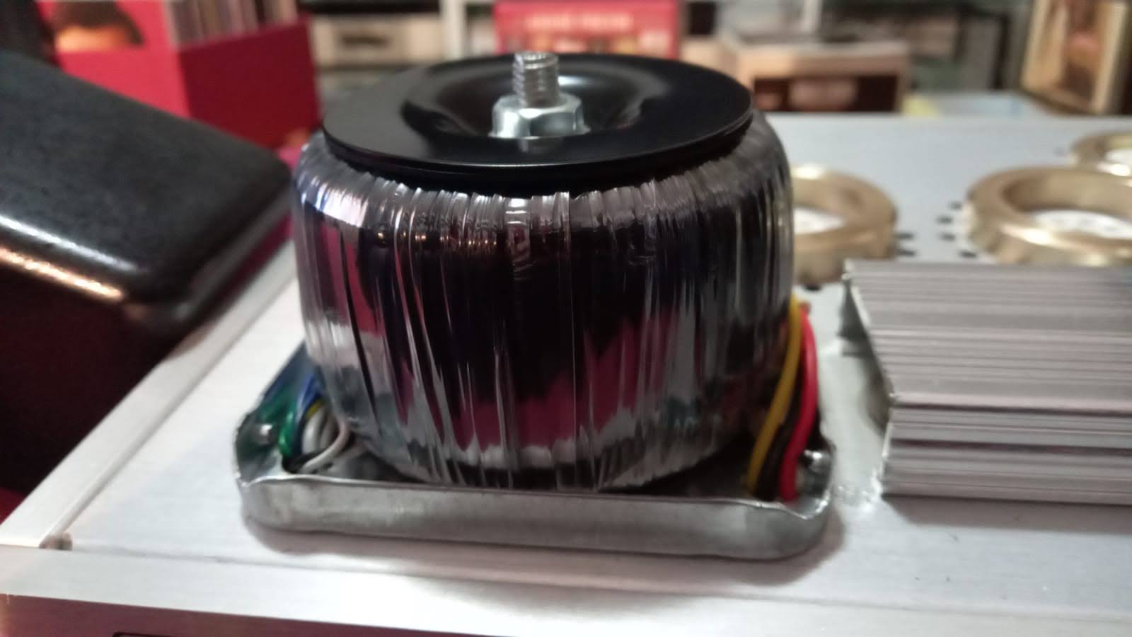
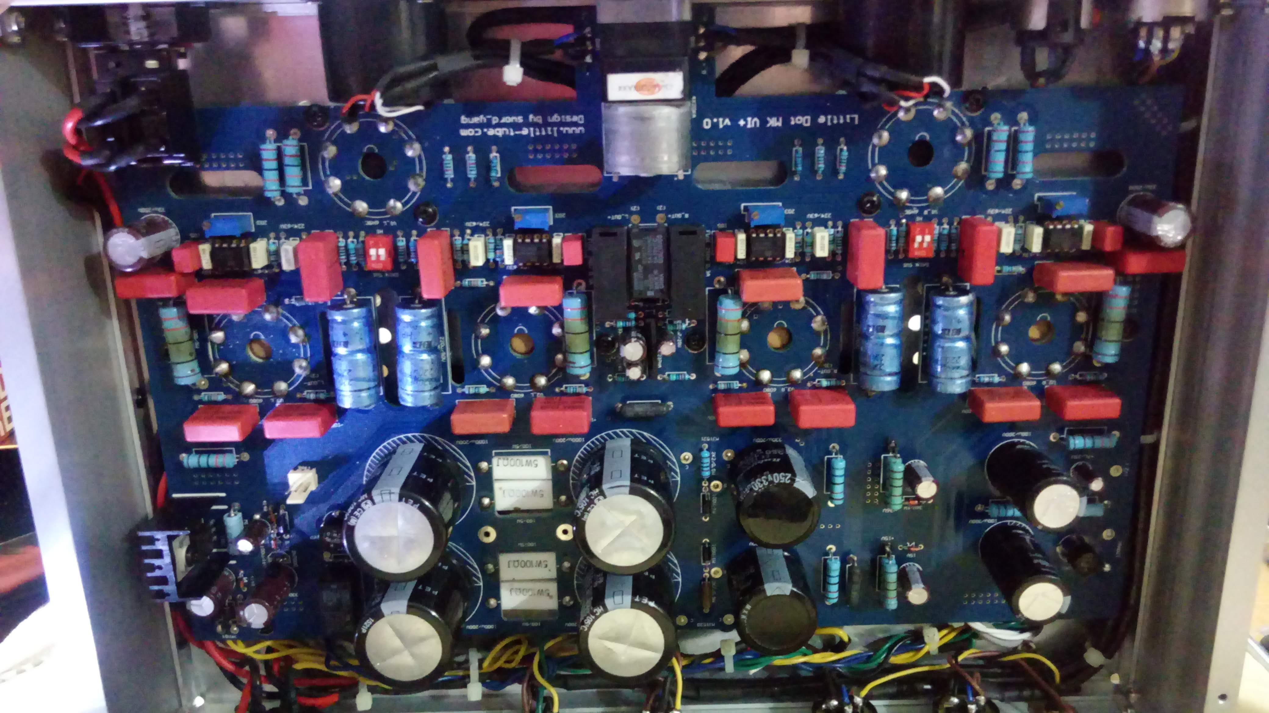
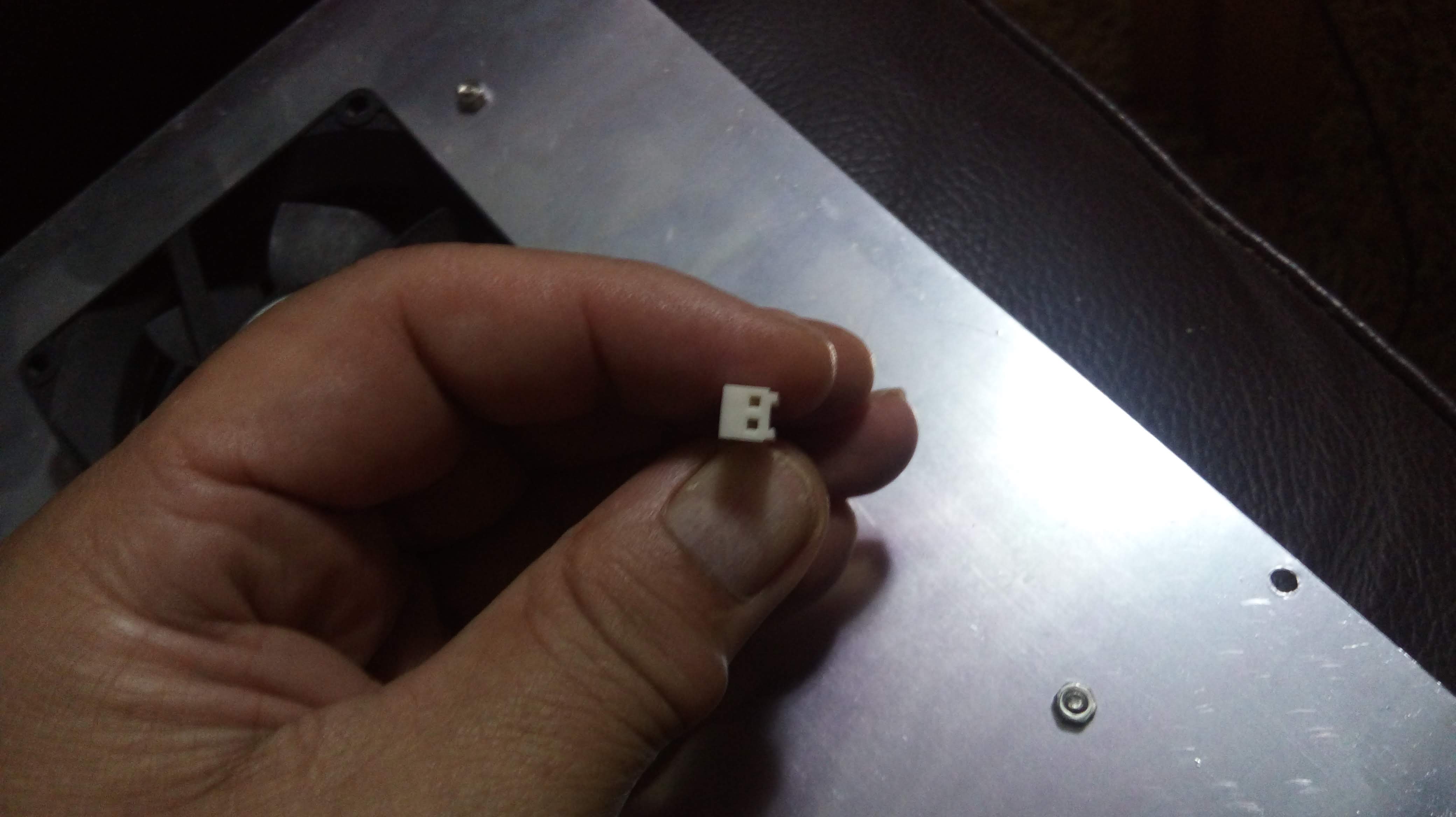
I am assuming this tiny 47uf cap is still installed?

Cant see from your pic:
 
Sep 14, 2015 at 7:31 PM Post #2,117 of 2,724
I have not touch the small 47uF cap, yes it is there.
Here are my part list got replaced in my LD6+

Power supply section
2x EPCOS 100uF 450V capacitors (smoothing caps dor the two driver tubes, replaced the 100uF 450V Rubycon KXW)
2 x Kendeil 330uF 400V (replaced the 330uF 250V Nippon Chemicon KMH)
4x Vishay BC 1000UF 250V (replaced the 1000uF 220V Nichicon GG)
4x Vishay 100R 10W resistor (replaced the white 100R 5W)

The reasons for replacing the above caps are
1. Aus is 240V, sometimes it goes high up to 260V in my suburb
2. A concern of fake chinese cap used in the LD

Since I have replaced the PS caps, I may done wrong, that's why asking to confirm the plate voltages to the driver and power tubes. If the problems are not from the PS section, I could focus on the signal path.

If the voltage supply to the tubes are right, could I assume the autobias sections are working fine?

Loading resistors
8x Mills MRS12W 330R (why 12W but not the 7W, I was told that the Mills are over rated their spec, not sure here, just for a piece of mind)

Interstage capacitors
4x 0.68uF 600VDC ClarityCap MR (why not Mundorf? Read good review about the ClarityCap MR, concern the brightness of the silver oil type, over my budget for the silver/gold oil type)

The two meters work as it were, the left one lighted up, after three minutes, the right one kicked in, togehter with the left meter, current display as normal, 80mA or 80mV.

The problem I have now (after finding that there was a disjoint on the MB between the 0.68uF and the driver tube, that's why I have soldered two little yellow wires in between), the right meter kick in but not light up (no 12V supply to the bulb?), the hissing and noise all gone but absolute silent. Some grounding issue? Or the output protection circuity is not working?

Need more time, but at least I could focus on the signal path now.

If anyone has a sketch of the circuit, it would be very helpful. I'm trying to trace the circuit by folllowing the signal path and PS.

Well, how could I damage the MB? the biggest mistake I have made was disconnecting the wires from the PS side to access the back of the MB, and I have little room to do the soldering. For anyone who is planning to replace the loading resistors and interstage capacitors, just desolder the two L/R input cables (next to the volume control pot), and the whole MB could flip out for easy access of the MB, a lesson learnt.
 
Sep 14, 2015 at 10:16 PM Post #2,119 of 2,724
I think I found your problem...
Hold on while I post aome pics...
 
Sep 14, 2015 at 10:46 PM Post #2,120 of 2,724
It is always a wise practice to take "BEFORE: Pics...

More SO important than "after" pics, so as to compare not only the work, but really,
The WIRING..

Look at the wiring of your voltage regulators to the board:

Beautiful clean work, no doubt..


Now lets look at another mk6 amp BEFORe it has been altered:

Notice anything?..

Yes, the blue and green wires from BOTH volt regulators in your amp are reversed...

Luckily, the nature of this amp is hard to actually break it..
I actually fixed my amp about THREE times already,
without having to replace parts...

So I expect normal operation once you fix those wires..

Still cant figure how you broke board trace from your coupling caps..

And I doubt highly that your right meter light not working..

Goodluck!

Edit:
Also side note..
Your board has all quality resistors,
So it was made before the "downgrade" to the cheapo blue resistors..
:)
 
Sep 15, 2015 at 1:51 AM Post #2,121 of 2,724
...
And for your information, the $5K is not sexy anymore ... think $10K and more => Ex :Viva Egoista "845" monster :
http://vivaaudio.com/


Hmmm...

Anybody have one of these, to pit up against mine?
I need a fancy name like that.
:p


Also, I have decided to upgrade my coupling caps yet again,

As coinmaster cannot be the only one to have all the fun around here...
:wink:

At this point, I have better everything than both you and Redge lol.

*$nip*
...

Hey!
Just a min there! Lol.

U wanna be like me?
U need:
1-20guage $ilver wire (shielded) for input.
2- NorneAudio High purity OCC Cu 22awg, for output.
3-blackgate eletrolytics.
4-Mills MRA12 in power supply.
5-TWO "IXYS FRED" High performance 600v/22amp rectifier bridge with fast recovery diodes)
6-All SYNERGISTIC RESEARCH fuses, RED SR QUANTUM FUSES.
7- $1300 for 6 best tubes in catagory, for an MK8.
8- lots & lots of fairy pixie dust...

----


You have:
1- all the *redacted* (most important) mods for mod thread.
2- larger components for most optimal gains..

You see you made me spill some beans.
:wink:

Anyways, its not just "size" that matters...
Its the whole "package"...
Where have I heard that before?
:p
 
Sep 15, 2015 at 3:06 AM Post #2,122 of 2,724
Lol both you and Redge got mad when I said that 
tongue.gif
 
Besides, most of those things you listed either don't or barely make a difference in the sound quality am I right? I'm pretty sure you said those resistors and black gates did nuthin' to the SQ. I have no idea what a "high performance rectifier bridge" is 
confused_face(1).gif

I'll take some of that wiring though.
 
As for tubes. I just bought two mullard 6080s, two tung sol 5998s, two bendix 6080s, and two tung sol 6sn7 round plates. I'ma have a good time with tube mixing fun 
bigsmile_face.gif

 
Sep 15, 2015 at 4:03 AM Post #2,124 of 2,724
Quote: Coinmaster:
...Besides, most of those things you listed either don't or barely make a difference in the sound quality am I right?


Exactly!

Thats why Understanding the amp is essential,
and why it would also be so great if we had the schematic...

Nevertheless, its not brain surgery and so not impossible, thanks to Redge78 for most the ground work and number crunching..

Yet I also told you,
the re- wiring of stock cable,
is another considerable gain not to be ignored.

For tubes I could have gotten away with much cheaper solutions at $200 for only a 5% less difference...(!)

Good thing the MK8 doesnt have as many tube rolling options...(!)

Oh, and I didn get mad,
But it is your fault I am upgrading further, to keep up lol
:p


Dear Maxx134

That's excellent found, wish that would fx the problem, will try out tomorrow as I have left my LD at work place.

Big thanks again.


Your welcome and goodluck!
:)
 
Sep 15, 2015 at 5:09 AM Post #2,125 of 2,724
Dear Maxx134

That's excellent found, wish that would fx the problem, will try out tomorrow as I have left my LD at work place.

Big thanks again.

Maxx's probably right but you still need to check things. Those LD guys could have just soldered things that way.
Yhat's good practice anyway.
 
You have two transistors , is the wiring colors symetrical ? If not, it's a good hint that's a "Maxx problem"
You also can do the measurements I askes above : from (E)mitter and (C)ollector pins,
When things are running properly, both sides read the same measures (roughly 135Vdc (C) and 105Vdc for (E)  for the MK8se)
 
Sep 15, 2015 at 8:14 AM Post #2,127 of 2,724
Redge78, Quote:
f not, it's a good hint that's a "Maxx problem"


Yes Redge78,
I have looked at bottom of pictures,
which shows the positioning of the wires as well..

So yes he has his wires reversed,
And yes, voltage measurment is ALSO most important.
Everything is exposed/revieled the voltage measurements..

Redge78 is correct about Little Dot amps using different colors at times,
To I GUESS to whatever they have available.
I have seen different color wires in MK8 amps,
Which is why I double checked with the positioning of the regulators outputs, as well as the colors..
:)

Hey, wait!
How you know I have a problem with the colors?!
I have a problem with everythning...
:wink:

Also , when I see a person upgrade with such meticulous detail/scrutiny in being so neat,
It is a dead give away thet the cause is most likely an error or oversight,
And not an actual part failure.
Yet lets hope nothing broke!
:)
 
Sep 16, 2015 at 9:15 AM Post #2,129 of 2,724
An update of the fault finding for my LD6+

1. The voltage to all driver tubes are correct
2. The fault did not appear to be related to the wiring of MJ15020/21

I was suspecting that there was something wrong related to the output relay protection circuit. The design of this protection circuit was for the +ve output from the L/R channel only. There was no protection for the -ve output. The -ve output was wired directly from pin#3 to the headphone output socket. The +ve ouput was wired from pin#3, through the protection circuit and then to the headphone output socket. So you could see two fuses only which were next to the relay.

What does it means? If you are running your headphone in balance mode, your headphone is not protected from current overload. So why not just bypass the protection circuit for better sound?

To test my amp, I used the single end output, which means testing for the +ve signal path only.

Before the second meter kicked in
1. I could hear musics coming out from the single end output (+ve signal), though the volume was very weak, and I could change the volume by using the volume pot
2. This mean the driver stage was working normal, right?
3. I have measured that there were no plate voltages applied to the power tubes yet
4. I also monitored the voltage across the diode behind the relay of the output protection circuit, it iwas 12V

At the moment the second meter kicked in
1. Plate voltages applied to the power tubes as it should be
2. However, musics was cut off at the same time
3. Protection circuit was activated, voltgae across the diode behind the relay drop to 0V from 12V
4. No cut off of the plate voltage applied to the power tubes
5. Voltage drop across 330R were normal, no sign of current overload acrross the 330R

Finding
I could not hear any musics from the single end headphone output because the output protection circuit has been activated.

What I need for help
1. Please confirm that you could hear the musics before the second meter kick in
2. If you could, measure the voltage across the diode behind the relay before and after the second meter kick in, just to confirm that it should be always stay at 12V

I will bypass the protection circuit or wired the +ve output directly to headphone output circuit to check if I could hear any musics after the second meter kick in?
 

Users who are viewing this thread

Back
Top