Little DOT MK III Mods??
Mar 27, 2018 at 2:43 PM Post #181 of 200
I believe this will be my last post on the upgrades / mods. I had another go at it and changed the PS caps as well. I replaced the 3 x 280uF nippon chemi-con caps with 3 x Nichicon 330uF caps. I also bypassed the 0.68uF output caps with 0.01uf Vishay 1837.

The results, which I credit mostly to Vishays, are astounding. The piano notes go high, and have weight behind them and they decay beautifully. The bass is still tight and authoritative with my Paradigm Studio 60v5. I am very happy with these changes. I haven't had a chance to try how this setup will sound with my Senn HD 700s.

In summary, this is what I've replaced on LD MKIII v4 board:
1. Replaced the two crappy orange film generic looking things with 2 x 0.68 Mundorf Mcap Evo Oil Aluminum.
2. Replaced the PS bypass generic looking orange crap with 2 x 0.47 Vishay MKP X2 safety caps.
3. Replaced 4 x Ero 1840 0.22uF with 4 x Mundorf Mcap Evo Oil Aluminum 0.22uF.
4. Replaced 3x PS caps Nippon chemo-con 280uF to Nichicon 330uF.
5. Bypassed 2 x 0.68 Mundorfs with 0.01uF Vishay 1837.

All of this fits in the case. Although, it takes forever to get things back in again.


------------------

I
Alright. Done with the second stage of upgrade. This is what I did in this part:

1. Replaced the two crappy electrolytic generic looking things with 2 x 0.68 Mundorf Mcap Evo Oil Aluminum.
2. Replaced the PS bypass generic looking crap with 2 x 0.47 Vishay MKP X2

It took me good 2.0 hours to do this minor upgrade, since Mundorfs are big, and it was a challenge to close it back. I ended up unsoldering all wires, got the board in, and then pulled in each direction and attached wires on each end. I ended up taping the leads because they may touch the sides. But, once in, there's good 1 mm space between the LD bottom and the caps - so all good.

Results:
After the initial upgrade of the 4 x .22uF Mundorf Evo Oil Aluminum coupling caps, the sound became really thin. So much so that Louis Armstrong sounded like Stevie Wonder. I am exaggerating a little bit. But really, the lower mids completely disappeared. I suspected that the caps were too small, and it was acting as a filter, by truncating lower frequencies. The bass became boomy. The highs were brilliant, airy and spacious.

I suspected because of those generic caps, there was something off. So, I ended up up upgrading the PS bypass caps as well.

After this upgrade, the mids are back! The highs are airy. The piano notes seem to hang in the air as they decay, it's beautiful. Louis Armstrong sounds like himself again.

One thing that has changed though, and that's baffling is that the volume is too low now. So I had to adjust the gain to 4, by toggling the switches. Before the upgrade, I was driving it by having the pot set at 12'0 clock. Now, I am getting the same volume at 3'O clock. Not sure what's the cause.

The sound's great though! Also, the noise floor has sank quite a bit, and there's much less ambient noise.

Here's a photo of the board:
U02idJY.jpg
 
Mar 28, 2018 at 6:08 AM Post #182 of 200
Is it possible to test whether the Mk3 is working properly before I undergo the process of pushing it back into its casing? I have a hum issue that I'm trying to rectify and have taken the board out and would prefer not to have to do it again.
 
Mar 28, 2018 at 1:21 PM Post #183 of 200
Is it possible to test whether the Mk3 is working properly before I undergo the process of pushing it back into its casing? I have a hum issue that I'm trying to rectify and have taken the board out and would prefer not to have to do it again.

Unfortunately, I don't know the answer to this, and I personally wouldn't recommend testing it out of the casing due to safety reasons. However, I have couple of tips that may be helpful:
1. The hum: I had a hum and it turned out it was related to the power socket and ground issues. Once I plugged my DAC and LD to the same socket (via extension chord), so they were using the same ground, the hum went away. Also, I use my LD as pre-amp, and I saw the same thing when I connected it to the power amplifier. The solution was again connecting them to the common ground on the same wall.
But, since you already have your board open, make sure that the ground wire is soldered properly.

2. Closing the LD with relative ease:
I have found that the easiest way is to follow the following steps:
a. When putting the board back, make sure the only wires that are connected to the board are the power wires going to the power tubes, and the ground wire. All other wires at this point should be de-soldered and disconnected.
b. Insert the board from the back-side, and wiggle it pass the nut/bolt thing under the PS housing. I ended up using a plastic knife as a shoehorn to hold the wires down, and it works remarkably well.
c. Get the board out the other side, enough of the way so you can solder the power wires for the driver tubes. And then, the audio channel wires. This of course means, that you will already have to have the power wires for the driver tubes coming out of the other side, before you insert the board back in. Audio wires on the other hand are stiff and can be pushed in from either end when you are ready to solder them.
d. Now push the board back in and out the back-end about 1/4th of the board. At this point, you will solder the power cables to the caps, the power socket, and the audio signal cables to the RCA jacks.
e. Final step. Push the board back into it's place. Add 4 screws to hold the board up, and then connect the volume pot (assuming you have a socket based board).
f. Close the rear and front panels.

Good luck!
 
Last edited:
Mar 28, 2018 at 8:44 PM Post #184 of 200
SonicJedi, thanks so much for this detailed and helpful response. I'm definitely going to give your method a try in the next couple of days.

As for the hum, I did try different outlets (and different buildings) and had only the LD plugged in. So it appears that it wasn't a simple ground loop problem, which I originally thought it was when I bought the amp.
 
Aug 16, 2018 at 3:59 PM Post #185 of 200
Stevebol,

Looks like the soldering quality is very poor not only on my MKIII. My clumsiness did not help either I guess :wink: 
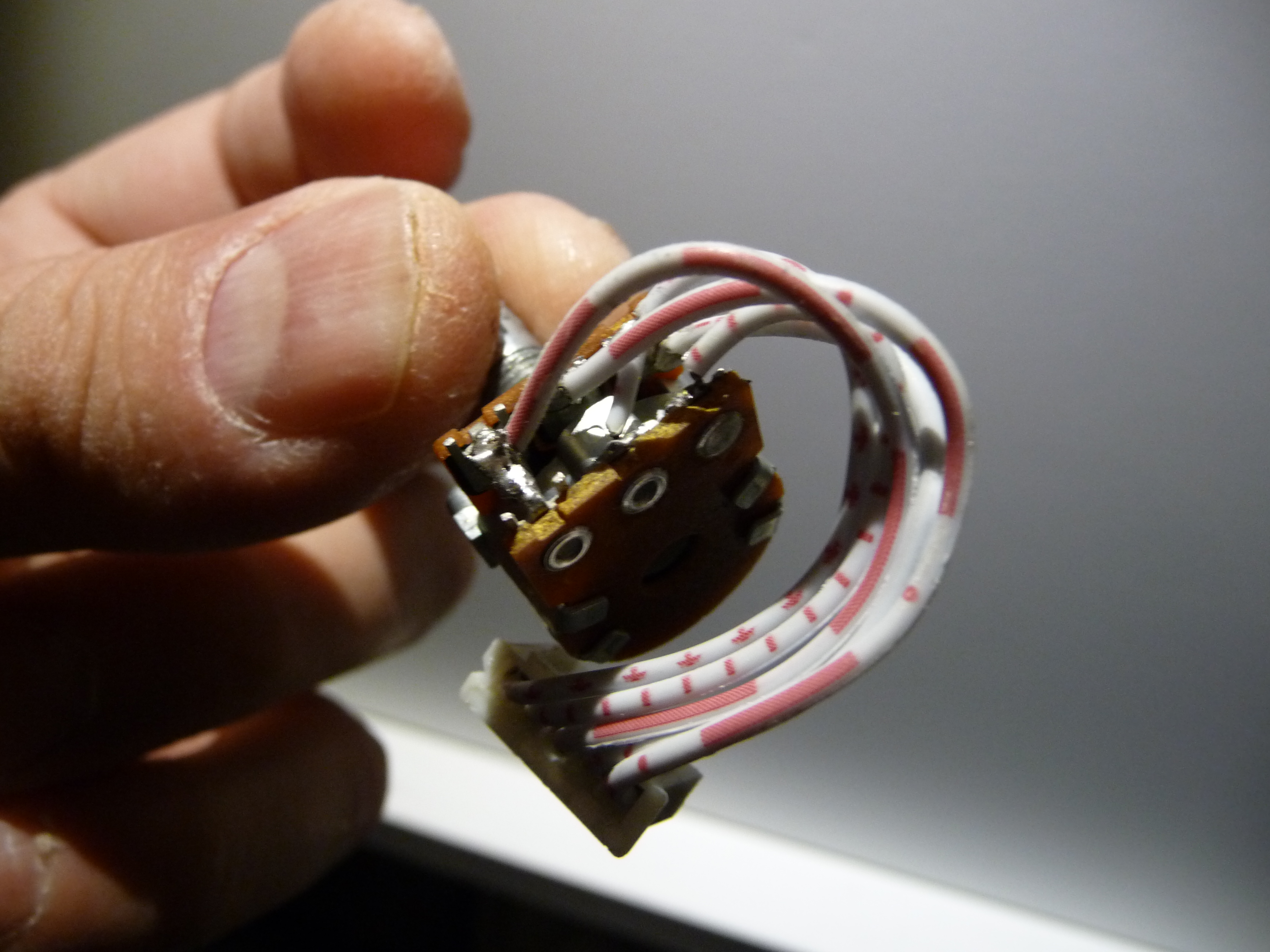
I think I figured out the pot wiring. It works fine... sometimes... well... I loose the left channel when I touch the pot in an improper manner :wink: I had some problems with the pot before and I assume it got damaged during the process of rewiring. I’ll check my soldering job later but I’m quite confident I did a decent job with my soldering iron.

Here is a key/legend for the rough sketch I did:
O – orange
WO – white orange
B – brown
WG – white green
G - green

Bear in mind I have never consulted the wiring with anyone and it is my educated guess only. Do not attempt this at home unless you are entirely sure and confident bla bla bla... :wink:


http://img848.imageshack.us/img848/8601/copyofdsc05647.jpg

http://img405.imageshack.us/img405/7887/copyofdsc05652.jpg

http://img641.imageshack.us/img641/3722/copyofdsc05763.jpg
Hi I realise it’s been a decade since you wrote this but could really do with some help with exactly the same issue. Do you have any pics of the correct wiring on the potentiometer? all the wires fell off as soon as I removed the front cover :frowning2:
Many thanks
 
Aug 16, 2018 at 7:58 PM Post #186 of 200
Hi I realise it’s been a decade since you wrote this but could really do with some help with exactly the same issue. Do you have any pics of the correct wiring on the potentiometer? all the wires fell off as soon as I removed the front cover :frowning2:
Many thanks
Got a few pictures this from MK3 pot LD POT 001.JPG LD POT 001.JPG LD POT 002.JPG LITTLEDOT MK3 Potentiometer wiring.jpg
 

Attachments

  • LD POT 003.JPG
    LD POT 003.JPG
    2.1 MB · Views: 0
Aug 17, 2018 at 4:20 AM Post #187 of 200
Thanks so much for the reply. My wiring colours look different to yours - I have Green, Blue, White, Black and Red coming out of the plug - which I assume corresponds to the 1-5 in the diagram above. Time to get my soldering iron out and give it a try

Thanks again
 
Aug 17, 2018 at 6:01 AM Post #188 of 200
I needed this info a while ago. The wiring coloration (or lack of it) made the whole process a bit more time consuming than necessary, but I found that little colourful diagram that @MIKELAP posted to do the trick for me. This pot was a little trial-by-fire situation for an amateur solderer like myself. I ended up changing the wiring to solid colours just in case I ever have to do it again.

Good luck.
 
Aug 17, 2018 at 1:05 PM Post #190 of 200
Thanks - yes my clumsy soldering will certainly be put to the test !!

Thanks again

Simon
Couple of suggestions:
1. email Sword Yang (little_dot at vip163.com) if you still need help. He's pretty responsive.
2. Take this opportunity to drop in a new and better quality pot. It will make a noticeable difference to your output. I recall that up to 21mm pot would work. Look for a 100k Alps original on eBay. Regardless of if you go for upgrade or not, make sure to fill and cover the wiring with silicone gel for galvanic isolation.

best of luck!
 
Aug 17, 2018 at 2:21 PM Post #191 of 200
Couple of suggestions:
1. email Sword Yang (little_dot at vip163.com) if you still need help. He's pretty responsive.
2. Take this opportunity to drop in a new and better quality pot. It will make a noticeable difference to your output. I recall that up to 21mm pot would work. Look for a 100k Alps original on eBay. Regardless of if you go for upgrade or not, make sure to fill and cover the wiring with silicone gel for galvanic isolation.

best of luck!
Thanks so much for the help - just ordered a direct replacement and what I think is a better one from eBay

https://rover.ebay.com/rover/0/0/0?mpre=https://www.ebay.co.uk/ulk/itm/362308916423

Fingers crossed :)
 
Feb 12, 2019 at 2:11 PM Post #192 of 200
Quote:


Concerning the 'missing' brown capacitor you could check the board to see if there are two empty soldering holes. (Probably close to the existing capacitor). Every component in the design should have a small text printed just next to where it's placed in the design (like '100K' for a resistor or '33uF 250V' for a capacitor). So if there is only one text with the '33uF 250V' printed you shouldn't worry.

Here you can see the LD MKIII board but it's the vers. 1 so it's not much help as there can be significant changes in the design:
http://www.littledot.net/forum/viewtopic.php?f=9&t=815&sid=ae7df9704ce470031d3523cbaf8f435d

Of course you can always drop David a line for help. He's usually quick with an answer.


Sorry for bringing up a decades old post but I took a look at my v2 board and and there is an empty capacitor slot and it’s does have the text underneath confirming that there should be another capacitor of the same size and type. I’m in the process of refurbishing and upgrading components on my mkiii after noticing two of the large 330uf caps were bulging.
 
Feb 20, 2019 at 3:11 PM Post #193 of 200
Sorry for bringing up a decades old post but I took a look at my v2 board and and there is an empty capacitor slot and it’s does have the text underneath confirming that there should be another capacitor of the same size and type. I’m in the process of refurbishing and upgrading components on my mkiii after noticing two of the large 330uf caps were bulging.

I'm sorry I can't quite comment on that as I have another version of the pcb - the mkIV. But as I said, try to email LD support they're usually responding.
 
Last edited:
Feb 27, 2019 at 7:47 PM Post #194 of 200
Not sure if anyone found posted this already, but that connector for the volume pot that's on the main PCB is a JST XH series connector. I was considering replacing the header and wires with a better one but i think i may just solder the pot wires directly to the main PCB. The JST XH plug is just too loose for my liking.
 
Last edited:
Feb 28, 2019 at 3:24 PM Post #195 of 200
Is there a reason why you guys are using 0.47uf x2 film capacitors in the rear by the big electrolytics? The protection caps that came on my V2 were Carli .047k 275v MPX40/100/21 x2 film capacitors. I'm no expert but doesn't the K indicate 10% tolerance and the .047 indicate that it's .047uf? It says on the PCB under the cap 47n 250v. 47 nanofarads = 0.047 microfarads. Or am i completely missing something here? http://kaizerpowerelectronics.dk/theory/capacitor-code-table/
 

Users who are viewing this thread

Back
Top