Little Dot Mk II Rebuild
Dec 4, 2020 at 1:38 AM Post #16 of 67
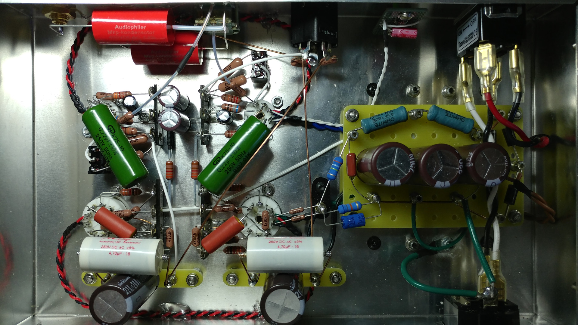
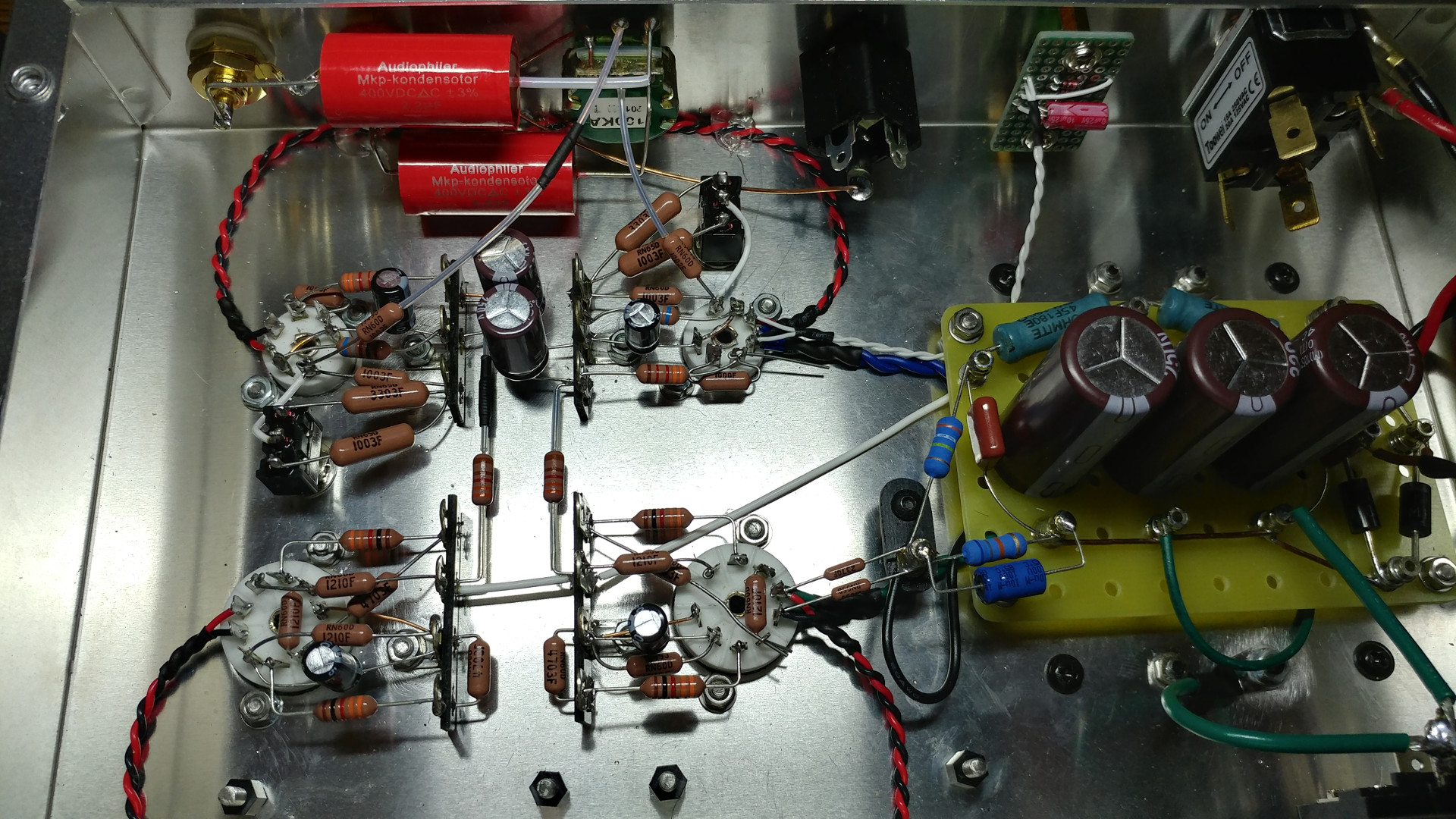
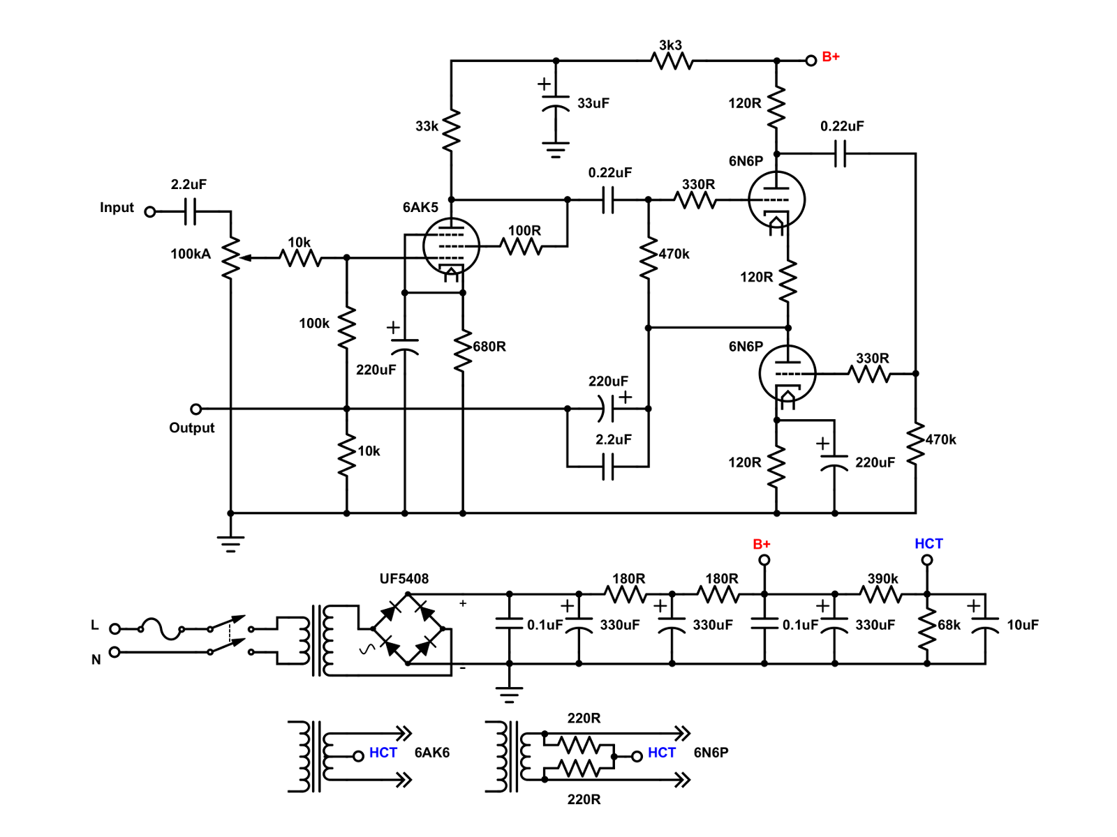
Doh! I cleaned up my Mouser project list last week, and deleted a bunch of them, this one included. However, all the components are in the schematic above. Starting with the power supply, the 2 180 Ohm resistors are Ohmite 45F180E, wirewound, rated at 5 W. The filtering caps are United Chemicon KXJ, rated at 250V. The two resistors that form the voltage divider for the heater center tap can be 1 W whatever. The bypass capacitor is 10uF, 100V; I used what I had on hand which was a Vishay. All the resistors in the amp are Vishay RN60 or CCF60. CMF60 will also do. The RN60 are military rated for 1/4 W, but for civilian use, they are actually 1 W resistors. As for the coupling caps, any polypropylene cap of a reputable brand should do. I would use caps rated for at least 250V. The output coupling electrolytics are Nichicon UPW, chosen for their low impedance nature.

One note: Because I'm using a stepped attenuator, I was able to move the input coupling capacitor to before the attenuator. If you are using a regular potentiometer, I'd keep it on the wiper to avoid any DC from the grid of the 6AK5. It probably won't matter at first, but eventually, the pot will become scratchy from the DC.
Thanks for that. Looking forward to starting.
 
Dec 4, 2020 at 2:37 AM Post #17 of 67
@drteming

thank you!

... now it's time for stupid question... : do you think this DIY solution improve the sound quality of an amount that justify the effort or it was mainly for fun (that is in any case a very serious thing) and because of the torture you have done in the past at the original circuit?

... less stupid question...: roughly... how many bucks?
 
Last edited:
Dec 4, 2020 at 4:54 AM Post #18 of 67
@drteming

thank you!

... now it's time for stupid question... : do you think this DIY solution improve the sound quality of an amount that justify the effort or it was mainly for fun (that is in any case a very serious thing) and because of the torture you have done in the past at the original circuit?

... less stupid question...: roughly... how many bucks?
One of the reasons I'm going to do it is to replace the 6n6 sockets with octal. I prefer 6sn7s on the back line. My tuppence worth is that uprating the components especially the coupling caps will make a significant difference. And yes, it will be fun too.
 
Dec 4, 2020 at 6:36 AM Post #19 of 67
@drteming

thank you!

... now it's time for stupid question... : do you think this DIY solution improve the sound quality of an amount that justify the effort or it was mainly for fun (that is in any case a very serious thing) and because of the torture you have done in the past at the original circuit?

... less stupid question...: roughly... how many bucks?

It was definitely for fun. I didn't have the original to do a direct comparison. I can't go by memory, because it has been a few years since I had listened to the original amp, and I didn't bother to fire it up before I tore it apart.

The main cost of an amp build is in the transformers. There's no output transformer, and the power transformer is already there. The most expensive part after that was the chassis, which under $15. I don't know the exact total as I had a bunch of the parts on hand (most of the film caps), but I'd say everything was under $40. You can go way beyond that if you go nuts and get "boutique" caps.
 
Dec 4, 2020 at 6:42 AM Post #20 of 67
Word of warning:. Even though this is a little amp, there are some lethal voltages, especially with the trio of the 330uF caps. Make sure you read up on the basics and safety of tube amps before trying anything. Never probe around with your fingers when the amp is on. When it's off, be sure that the large caps are discharged before working on it.
 
Dec 4, 2020 at 5:55 PM Post #21 of 67
One of the reasons I'm going to do it is to replace the 6n6 sockets with octal. I prefer 6sn7s on the back line. My tuppence worth is that uprating the components especially the coupling caps will make a significant difference. And yes, it will be fun too.

that is my idea too but unfortunately I remember a post I’ve read somewhere about a MK2 mod and the result was that improving power supply stage gave much better (more positive influence) to the sound then updating the output caps... honestly I have no idea about how to improve power stage... I think that post is almost at the end of the discussion about LD MK2 here in this forum... I’m going to search there right now
 
Dec 23, 2020 at 3:18 PM Post #22 of 67
that is my idea too but unfortunately I remember a post I’ve read somewhere about a MK2 mod and the result was that improving power supply stage gave much better (more positive influence) to the sound then updating the output caps... honestly I have no idea about how to improve power stage... I think that post is almost at the end of the discussion about LD MK2 here in this forum... I’m going to search there right now
Uprating any audio power supply is a good idea. I was thinking doing just that. I have a couple of Chinese 6Z4 rectifiers an wondered about using them instead.
 
Dec 23, 2020 at 4:35 PM Post #23 of 67
With a total current draw of about 36mA, I'm not sure how much benefit a beefier power supply will provide. But just for fun, I ran it through the Duncan PSU designer and came up with this:

LD MK II - 6X4.png


The 6X4 rectifier is electrically the same as the Chinese 6Z4, but different pin-out. The 220 ohm resistors on the plates of the rectifier will make it last forever and also allow the first capacitor to be bigger than the 40uF limit. The AC ripple at B+ is only 6 microvolts.
 
Dec 23, 2020 at 7:06 PM Post #24 of 67
With a total current draw of about 36mA, I'm not sure how much benefit a beefier power supply will provide. But just for fun, I ran it through the Duncan PSU designer and came up with this:

LD MK II - 6X4.png

The 6X4 rectifier is electrically the same as the Chinese 6Z4, but different pin-out. The 220 ohm resistors on the plates of the rectifier will make it last forever and also allow the first capacitor to be bigger than the 40uF limit. The AC ripple at B+ is only 6 microvolts.
Wow. That's beefier than I was going for. The data sheet shows 16uf smoothing. I'll breadboard yours I think. Thanks
 
Jan 10, 2021 at 5:55 AM Post #25 of 67
if you wanted to tinker, try a ccs (dn2540 are simple) in place of the annode resistor on the input stage.
 
Jan 10, 2021 at 7:13 AM Post #27 of 67
The basically work presenting a low (and ideally constant) impedance to DC, but a high impedance at AC. This gives the effect of using a very high resistance (to maximize gain for example) but without the drawback of a huge voltage drop or miniscule current performance.

They also let you be very precise in setting the triodes operating point , so you can pick a very linear spot.

You can also test them with a 9v battery so you can be sure you are going to sizzle the valves with a mistake. .
 
Jan 10, 2021 at 7:14 AM Post #28 of 67
Other tinkering opportunities, led bias the valves (you need to understand the operating point to pick the right led vf). I personally prefer this
 
Jan 10, 2021 at 3:54 PM Post #30 of 67
I've heard of that. I'll look into this a bit more as I'm still at the planning stage. Thanks
A yellow led should be good, normally they are 1.9v vf.

As the stages are decoupled,. CSS load of the first would be really simple to try, maybe start with a super simple single dn2540.i will have a quick look at the input valve datasheet and see what it's idling at
 

Users who are viewing this thread

Back
Top