Little Dot Mk II Rebuild
Oct 14, 2021 at 1:41 PM Post #62 of 67
hi

could somebody in this thread recommend a replacement transformer that will fit in the original enclosure.

Mine is making a hum/buzz that is slightly noticeable , i tried to place it away from any WiFi source but it doesn't help so i would like to replace it.

thanks
 
Oct 18, 2021 at 5:57 PM Post #63 of 67
the transformer enclosure is made by iron and connected to ground via screws holding it to aluminium main housing and, from there, to the ground contact in the main power connector… so… are you sure is the transformer or maybe could be something related to the tube you are using or the Wi-Fi source not properly grounded and/or shielded?
 
Oct 19, 2021 at 5:01 AM Post #64 of 67
the transformer enclosure is made by iron and connected to ground via screws holding it to aluminium main housing and, from there, to the ground contact in the main power connector… so… are you sure is the transformer or maybe could be something related to the tube you are using or the Wi-Fi source not properly grounded and/or shielded?
the sound is coming from the transformer, sound like a Magnetostriction effect to me. i have it will all kind of tubes i tested of various family. for the Wifi i tested close and far from any wifi source and i still have the sound. It is a second hand one that i bought on ebay so maybe the transformer just got a hit over the time.
Wanted to try to replace it with a non Chinese version as last approach.
 
May 29, 2022 at 7:40 PM Post #65 of 67
All done.

05 Finished Guts.jpg

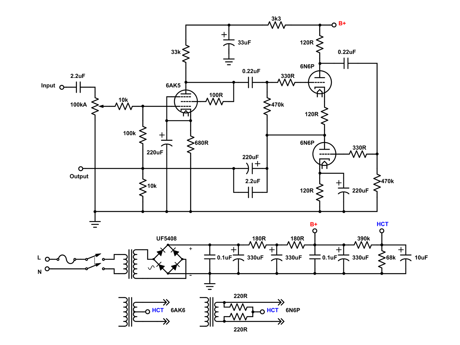
I revised the negative feedback scheme with a set 220k resistor and switched in 330k and 100k, for paralleled resistance of 132k and 68.8k. With only the 220k resistor there is an attenuation of -3.4dB, with 132K, -5.4dB, and 68.8k, -9.2dB. I have nicely matched Voskhod 6J1P-EV and Novosibirsk 6N6P in the amp, and I had forgotten how nice it sounds.

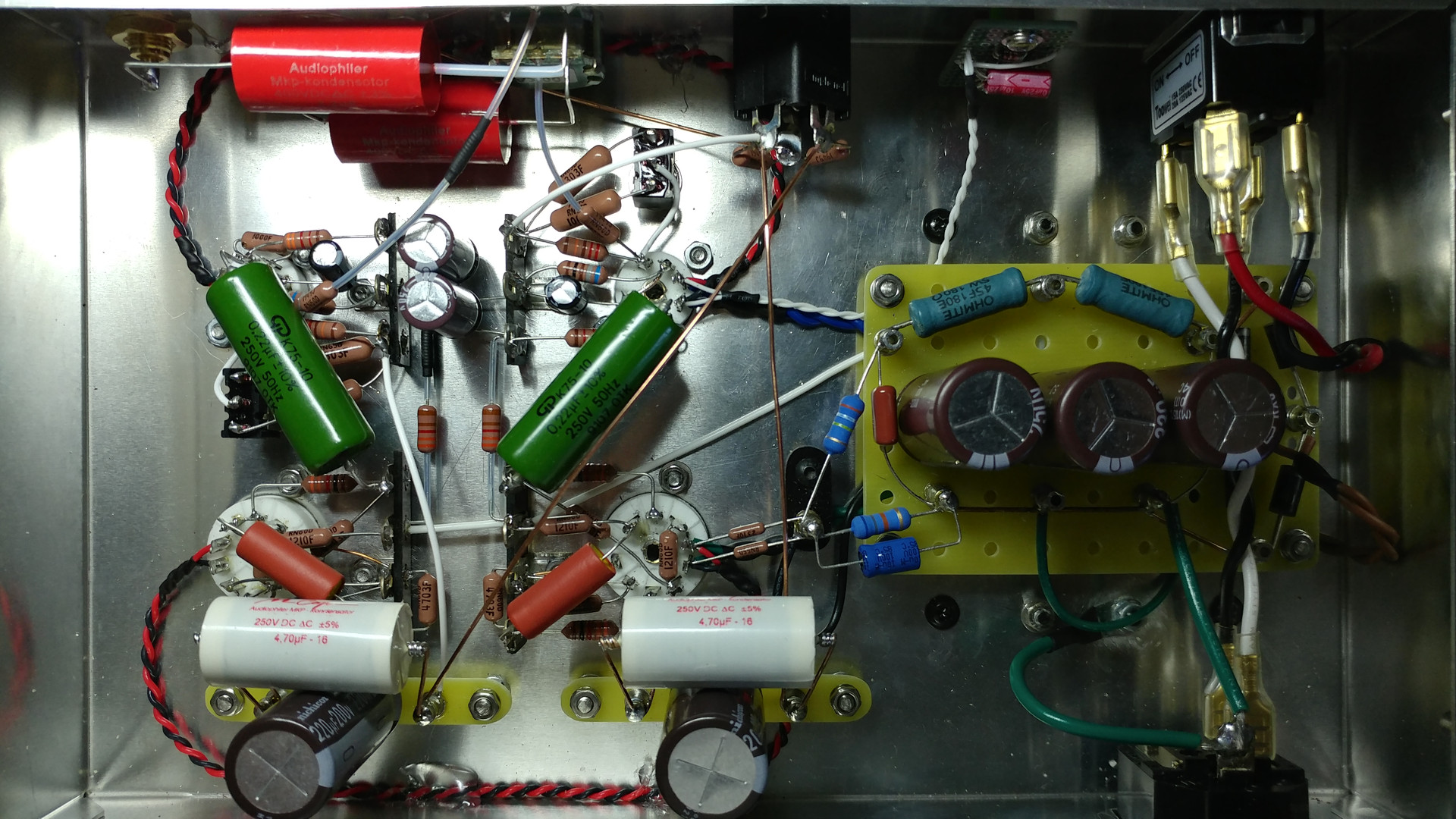
One final change, I upped the film cap on the output to 4.7uF.

LDmkII-mod.jpg

06 Outside.jpg

The ripple voltage to the 6N6P was 0.27mV and 3uV to the front section, so there's plenty of filtering in the power supply. No audible hum or noises.

The total resting power draw for the amp was only about 36mA. An interesting build can be done with a Hammond 269EX power transformer and a 6X4 rectifier tube with appropriate dropping resistors in the RC filtering circuit.
Hi, Met you over on DIY Audio and have been enjoying this thread here on your rebuild! I have a couple questions, and you seem like the right guy to ask. first, why did you move the coupling cap, in input, in front of the pot? I know resisters and caps can sound different based on order, but what was your reasoning and what did you notice? Second question, what is the B+ voltage of this amp, stock? Does that appear at the 220uF output coupling caps? What do you think would be the lowest voltage rated caps safe to use there? Thanks in advance!! Enjoy your ides here! Been playing with mine and have some good results so far.
Jason
 
May 30, 2022 at 2:25 PM Post #66 of 67
The coupling cap at input was initially after the potentiometer. That's usually what I do for my amp builds. The coupling cap keeps the little bit of DC from the grid away from the pot. The DC can eventually cause scratchiness in the pot. That being said, I have a stepped attenuator in there, so I don't have to worry about DC causing problems. My kid took the amp to college, so the input caps are there as insurance against stupid things college kids do.

The B+ is around 190V in the original amp and in my rebuild. I did not change any values in the power supply. The 220uF coupling capacitor sees about 95V when warmed up and not the full 190V. However, I'd stick with at least 200V rated caps or higher for safety's sake.
 

Users who are viewing this thread

Back
Top