Kwak-Clock Mod
Mar 20, 2007 at 8:53 PM Post #31 of 99
Yeah, that is indeed an excellent price, but its the PCB board that kills you. Unless you make it yourself, and the geometry of the traces does matter considerably with Elso's design so unless you copy his, I don't know, I am sure there are a bunch of experts out there. You could just order it from him, but he charges a premium for his copyrighted design. If you do make a pcb board, make sure it doesn't copy his, and make sure you post it
biggrin.gif
 
Mar 20, 2007 at 10:14 PM Post #32 of 99
Looks like Mouser is out of stock on:
R1 1 resistor 1k 660-MF1/4DC1001F $0.03

But they have this in stock:
71-CCF55-1K $0.05

A circuit board could be generated by computer. Anyone want to simulate and model one?
 
Mar 21, 2007 at 3:57 AM Post #35 of 99
Quote:

Originally Posted by Crowbar /img/forum/go_quote.gif
There's a third option, which is to slave the transport clock to the DAC clock, but that means you need one more cable, from the DAC back to the transport.


This third option is really one of those internet myths as far as DIY goes, it hasn't been done sucessfully because it requires some complicated digital circuitry to do it right.
 
Mar 21, 2007 at 4:05 AM Post #36 of 99
Quote:

Originally Posted by regal /img/forum/go_quote.gif
This third option is really one of those internet myths as far as DIY goes, it hasn't been done sucessfully because it requires some complicated digital circuitry to do it right.


I call BS, and I can prove it: http://peufeu.free.fr/audio/extremist_dac/

There is also at least one other DIYer that did this, either from the headwize or diyaudio forums. The FIFO is actually a more complex option to properly implement, but has also been implemented (search diyaudio).
 
Mar 21, 2007 at 8:45 PM Post #37 of 99
kwakclock3.jpg


Wow...
 
Mar 21, 2007 at 11:00 PM Post #38 of 99
Lets stop arguing over the effectiveness of the Kwak Clock, because if you are in any form of disbelief, you simply haven't heard one. Yes, you crowbar.

So, lets shift from that subject to the design and possible group buy of a Kwak Clock PCB board. I will be working with Eagle, I am nearly finished inputting the schematic, once I have, I'll upload it so any and all may begin a pcb design.
 
Mar 21, 2007 at 11:14 PM Post #39 of 99
Quote:

Originally Posted by colonelkernel8 /img/forum/go_quote.gif
Lets stop arguing over the effectiveness of the Kwak Clock, because if you are in any form of disbelief, you simply haven't heard one. Yes, you crowbar.


What are you smoking? Read what I wrote: nowhere am I arguing against the Kwak Clock. I use one myself, even had ICM manufacture a custom crystal for me to use in the circuit, and I'm on the same forum Elso Kwak is (diyhifi.org) without having had any argument with him.

The arguments I made is first about attaching it properly, and second about regal's unfounded posting about clock injection to the transport. None of these have anything to do with the clock design itself, so I'd love to know where you pulled that one from. Care to explain?
 
Mar 21, 2007 at 11:54 PM Post #41 of 99
I'm still waiting for you to back up your accusation, or apologize. Simply quote where it is I said or implied the clock is not effective, or show at least the minimum amount of manners needed to apologize.
 
Mar 23, 2007 at 12:20 AM Post #42 of 99
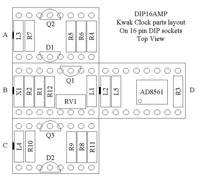
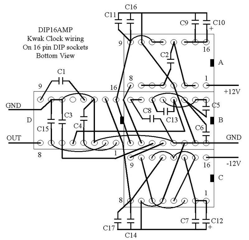
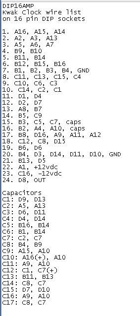
I did a parts layout, wiring diagram, and wire list for the Kwak clock on four 16 pin DIP sockets.
Mouser has the sockets (p/n 575-193316) for $0.98 each.

Socket "A" has the positive voltage regulator.
Socket "B" has the xtal circuit.
Socket "C" has the negative voltage regulator.
Socket "D" has the AD8561 and output circuit.

Solder the wires on the bottom of the sockets in order of the wire list.
Then the capacitors, then plug the rest of the parts on the sockets.

Here are the pics.

dip16kwakclkt.jpg


dip16kwakclkb.jpg


dip16kwakclkw.jpg
 
Mar 23, 2007 at 12:25 AM Post #43 of 99
In a high frequency circuit, PCB layout is critical, as the parasitic reactances of even short traces and wires have an effect. This rats nest is not going to give you anything near the optimal perormance possible by the clock.

The best option is to do this with surface mount parts on a PCB half the size of your contraption, with attention carefully paid to trace layout.
 
Mar 23, 2007 at 12:39 AM Post #44 of 99
Quote:

Originally Posted by Crowbar /img/forum/go_quote.gif
In a high frequency circuit, PCB layout is critical, as the parasitic reactances of even short traces and wires have an effect. This rats nest is not going to give you anything near the optimal perormance possible by the clock.

The best option is to do this with surface mount parts on a PCB half the size of your contraption, with attention carefully paid to trace layout.


Elso wasn't selling PCBs before. But 4 years ago, I decided to try out his design without a PCB. I used something called veroboard but it is still P2P.

VERY VERY BAD experience with all kinds of distortion.
 

Users who are viewing this thread

Back
Top