iM716 DIY Pod Removal (aka, Podectomy)
Nov 13, 2006 at 8:46 AM Post #62 of 352
Quote:

Originally Posted by jSatch
These are two different things.

Briefly, the P to S connector is a single, series, in-line resistor. This will attenuate volume (added resistance), and increase impedance. This change in impedance will change the sound sig, as seen in this thread to 'customize' the sound, and as used by Ety in their P to S connector.

The 'Hissbuster' (a series, R2, and parallel, R1, resistor) will attenuate volume without a change in impedance. This will increase the load the amp sees so you won’t hear the background hiss anymore, but will not change the sound sig of your phones.

These simple circuits, as in the Hissbuster, are utilized in crossovers (XO) in room speakers to equalize the output of the different speaker components (tweeter, mid, woofer) in a multi-speaker system without changing the sound sig of them.

If you have a decent speaker system, check the XO to the tweeter. Chances are it will have this R1, R2 circuit along with a capacitor in series for a 1st order XO. The cap is a high-pass device that cuts off lower frequencies at approx 6 db per octave. 2nd order (12 db per octave) and on up XOs, for faster attenuation, get a tad more complicated, as will the addition of notch filters, etc if utilized within the XO.

Clear?


An informative reply. Thanks!

Know I need to decide what to build to go between my hissy iPod shuffle and my CX300 (I am fairly happy with the sound sig, but would like to tame the sibilance a little)

I am interested why ETY want the adapter to change the sound signature of the ER4 when changing from a 4P to a 4S. Could they not make an efficient design (the 4P) with the sound they want then use the hissbuster arrangement to make them require more juice. Do we know if the ER4s has higher impedance units (armatures, not voice coils: I know little about armatures), or simply the adapter resistor built into the earpieces?
 
Nov 13, 2006 at 12:34 PM Post #63 of 352
Quote:

Originally Posted by Ace o' Spades
EDIT: Dang it vYu, got your post in before this one. Did you read the entire post?:


This is the schematic for a simpler (and therfore cleaner sounding) switchable HD-bass pod. The concept is extremely simple, but he challenge will be incorperating it into a pod of sorts that will look professional. If I decide to I can make one into an altoids tin just for fun, even though it will be a bunch of extra space for 4 resistors, a switch, and input/output jacks.

Schematic:
hi-fipodcopy.gif


I am getting loads of ideas in my head right now for this project. Maybe if I decide to put it into an altoids case I will use the extra space for Chu Moy's Crossfeed circuit...


Is there any way of incorporating this schematic into the original pod, removing what is no longer needed, and close it back again the way it was...thinking twice, that way the look will be inentical, you have no need of anything else, just a soldering iron and resitor that maybe are even soldered to the pod already, and it will look professional, sorry to water the soup but I hate those ghetto solutions, that look horrible, look to me is extremelly important, and I think is doable as well...BTW I no longer own a pair of those so I'm not talking becasue I need it, just wondering, as I know that for sure I'm not alone on that feeling....
tongue.gif
 
Nov 13, 2006 at 7:16 PM Post #64 of 352
Quote:

Originally Posted by Ace o' Spades
Well...I just looked up the price to make 2 of these boards. At $87, I might as well buy a new set of cans.


As Sovkiller mentioned, you could use the original pod. Could also use the switch. Dump the pcb board and junk vol pot and use discreet resistors, ie hard wired resistors.

With this set up you still might degrade the sound slightly with the switch, but not nearly as much as with the pcb board, resistors and vol pot of the original, IMHO.

You may want to try 33 and 68 Ohm resistors, which would somewhat parallel the Bass and HD modes, respectively.

Also, this would be a great little set-up to compare resistor values via A/B testing, ie, side by side.
 
Nov 16, 2006 at 5:53 PM Post #65 of 352
Picture of the poddless iM716.

Not from a good camera. Might redo. But will give you the idea of size reduction without pod.

Also, I haven't heat shrunk the heat shrink yet, although 'I think' the 68 Ohm resistors are gonna stay in.

Cheers

PB070002.jpg
 
Dec 10, 2006 at 7:36 PM Post #66 of 352
Oooh, quite sexy. I just picked up the parts to reterminate/podectomize my iM716. Hopefully it will go quite smoothly, the only worry I have is reterminating such small wires. Also, for the wire colors, red is right, and green is left? Just making sure... I really dont want to swap the channels by accident.
 
Dec 10, 2006 at 9:57 PM Post #67 of 352
I just finished. Wow! what a difference. Between the new jack and the 47 ohm resistors, these have taken a huge turn for the better in terms if durability, portability, and sound quality of course.

I really like the 47-ohm resistors, great bass impact and good treble.
 
Dec 30, 2006 at 11:25 PM Post #71 of 352
Quote:

Originally Posted by jSatch /img/forum/go_quote.gif
Maybe 100-Ohms next?


I finally got around to making a P-S adaptor for these with some leftover 47-ohm resistors from my original Podectomy project. This brings the impedence up to 100 ohms (or 99, but close enough). I seriously don't reccomend it. The bass almost dissapears, leaving a rather cold, lifeless sound even with a good amlifier backing them up.

I'd say the best values for this mod (in ohms obviously) are 22ohms, 47ohms, and 68ohms from my own input and what has already been said.
 
Jan 5, 2007 at 2:13 AM Post #72 of 352
Quote:

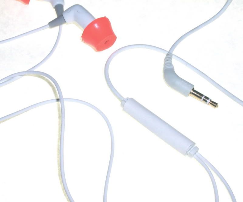
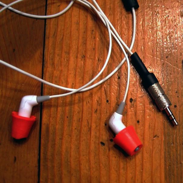
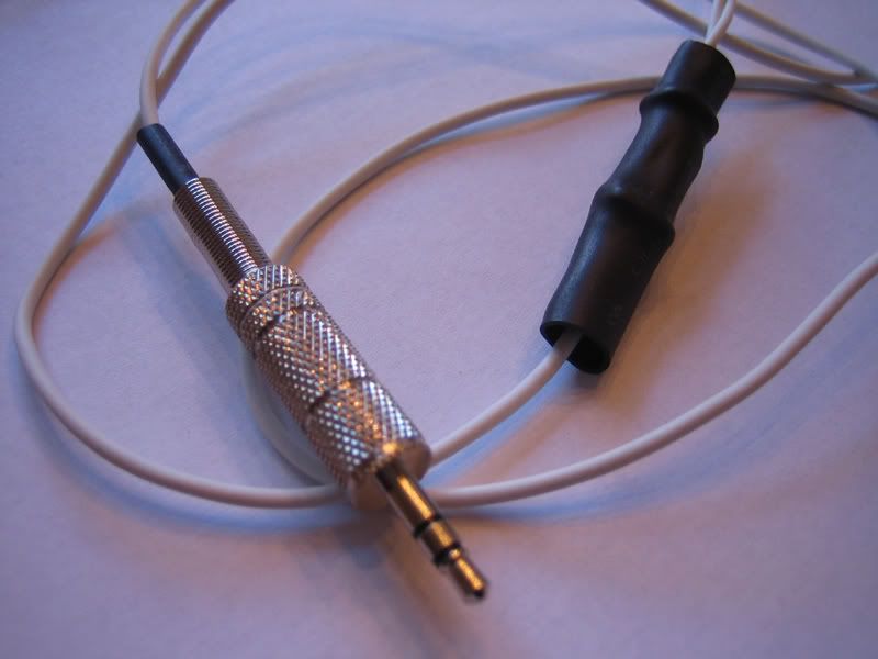
Originally Posted by Ace o' Spades /img/forum/go_quote.gif
I finally got around to making a P-S adaptor for these with some leftover 47-ohm resistors from my original Podectomy project. This brings the impedence up to 100 ohms (or 99, but close enough). I seriously don't reccomend it. The bass almost dissapears, leaving a rather cold, lifeless sound even with a good amlifier backing them up.

I'd say the best values for this mod (in ohms obviously) are 22ohms, 47ohms, and 68ohms from my own input and what has already been said.


Thanks Ace, saves me some time and energy.

Have you tried the 100 Ohm version with a real Hi-Fi rather than an iPod for a source?
 
Jan 5, 2007 at 5:13 AM Post #73 of 352
i did my pod mod about a mth ago. tried both 33ohm n 47ohm resistors. settled on the 33ohm juz coz it ran fine with the requiste volume juz off the headout of my ipod 5g. ampless, the depodded 33ohm iM716 sounded sweet and IMO, like a mini HD600.

another satisfied pod mod iM716 owner here, thxs to jsatch thread
biggrin.gif
 
Jan 9, 2007 at 1:17 AM Post #74 of 352
Quote:

Originally Posted by scottiebabie /img/forum/go_quote.gif
i did my pod mod about a mth ago. tried both 33ohm n 47ohm resistors. settled on the 33ohm juz coz it ran fine with the requiste volume juz off the headout of my ipod 5g. ampless, the depodded 33ohm iM716 sounded sweet and IMO, like a mini HD600.

another satisfied pod mod iM716 owner here, thxs to jsatch thread
biggrin.gif


Thank you for the kind words, I'm happy it worked out for you.

I think the strongest aspect of this mod, other than getting rid of the in-line junk components, is the ability to tune in your sound. I liked the 33, 47 and 68-Ohm resistors in-line. I ended up with the 68-Ohm resistors, but not by much, and that could easily change. Which you prefer is a matter of your own tastes, the music you listen to, and your own equipment.

Again, thank you for posting.
 
Feb 18, 2007 at 1:30 PM Post #75 of 352
i want my im716 modded too, but i have no experience in soldering n stuff. i've emailed moon audio for it to be professionally modded, but got no reply.

who else can i approach to do it for me for a fee? forum members, need a quick buck?
 

Users who are viewing this thread

Back
Top