iM716 DIY Pod Removal (aka, Podectomy)
Nov 10, 2006 at 1:48 AM Post #46 of 352
Quote:

Originally Posted by Ace o' Spades
This topic has inspired me a bit to make a tutorial for a DIY P-S connector. It should be extremely easy with a bit of patience and soldering skill.


Yup, should be a cake-walk.

Go for it Bro, and take some pics.
 
Nov 10, 2006 at 1:58 AM Post #47 of 352
Quote:

Originally Posted by CMasten
I can say that with the 33 ohm resistance now, that my IPOD 5g doesnt need any EQ at all anymore with these IEMs and I am really getting used to the tight bass and fast attacking treble, its pretty addictive
smily_headphones1.gif


Sweet.


Quote:

Originally Posted by CMasten
I could never find the right setting for my ears between the HD and the Bass setting on the POD... this DIY just rocks


Yeah, I had the same problem with the HD and Bass modes. Besides, the HD could sound hard and congested at times, and a bit thin, whereas the bass in the Bass mode sometimes had a peculiar quality to it. Some people called it muddy. I'm not sure. I thought it was more of an electronic, phasey kind of problem. I haven’t had a problem with either of these since.

Well, at least not yet…… (fingers crossed)

Later-
 
Nov 10, 2006 at 5:29 AM Post #51 of 352
Quote:

Originally Posted by jSatch
I think the amount of microphonics remains the same, or theoretically it should, but, and a very BIG BUTT, is that you don't have the pod swinging around, or even if anchored down, the wires moving around, nearly as much. Although you still here microphonics if you tap on the upper wires, the far lighter weight on the cord makes a big difference in the 'apparent', or real world microphonics, which are markedly decreased. Or at least that's my take on it.

If you wiggle the right wire near the pod do you hear the static or disconnection, or near the earpiece? If near the pod, it could fix the problem, if near the earpiece, well, need I go on?

In either case, you may want to take advantage of the warrantee period before chopping anything off.


it is near the pod. So you are telling me there is a chance??? I would do the warrantee thing, but i'm afraid i've lost the reciept :frowning2: I was thinking I could buy a new pair, use the reciept from that pair to return the old pair. Then i'd try and sell the extra pair. If i can solve the problem w/ this DIY, i'm gonna do it
 
Nov 10, 2006 at 9:29 AM Post #52 of 352
Quote:

Originally Posted by warmapplepie
it is near the pod. So you are telling me there is a chance??? I would do the warrantee thing, but i'm afraid i've lost the reciept :frowning2: I was thinking I could buy a new pair, use the reciept from that pair to return the old pair. Then i'd try and sell the extra pair. If i can solve the problem w/ this DIY, i'm gonna do it


If the wire is lose at the pod connection, and when you wiggle it there you go in and out of connection / static, there is a very good chance it is the pod wire connection. One less wire to de-solder to get the pod off during the podectomy. You are sure it is not the wire /earphone side? I've heard stories of bad connections at both ends. Not on the same phones, of course.

However, you won't be sure of this until you crack the pod open. Unless, of course, the wire falls out of the pod altogether when you wiggle it.
eek.gif
 
Nov 10, 2006 at 10:39 AM Post #53 of 352
Quote:

Originally Posted by Ace o' Spades
This topic has inspired me a bit to make a tutorial for a DIY P-S connector. It should be extremely easy with a bit of patience and soldering skill.


Would adding impedance to my CX300 help the hiss with the shuffle, or should I build one of these:
http://www6.head-fi.org/forums/showt...ght=hissbuster

Adding impedance (the P to S) or dropping the voltage (the hissbuster) basically
 
Nov 10, 2006 at 4:35 PM Post #54 of 352
My tutorial will be very simple. I will take about 1ft of CAT5 wire for the interconnect, and simple Ratshack 3.5mm jacks. For the resistors I am using 47ohm metal-film resistors left over from my CMOY.

Another thing I might try is soldering the resistors directly to the female plug's pins, since they are so small they should fit right in. As long as I solder the CAT5 to them first soldering won't be an issue.
 
Nov 10, 2006 at 10:04 PM Post #55 of 352
Quote:

Originally Posted by lipidicman
Would adding impedance to my CX300 help the hiss with the shuffle, or should I build one of these:
http://www6.head-fi.org/forums/showt...ght=hissbuster

Adding impedance (the P to S) or dropping the voltage (the hissbuster) basically


These are two different things.

Briefly, the P to S connector is a single, series, in-line resistor. This will attenuate volume (added resistance), and increase impedance. This change in impedance will change the sound sig, as seen in this thread to 'customize' the sound, and as used by Ety in their P to S connector.

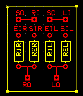
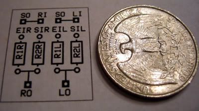
The 'Hissbuster' (a series, R2, and parallel, R1, resistor) will attenuate volume without a change in impedance. This will increase the load the amp sees so you won’t hear the background hiss anymore, but will not change the sound sig of your phones.

These simple circuits, as in the Hissbuster, are utilized in crossovers (XO) in room speakers to equalize the output of the different speaker components (tweeter, mid, woofer) in a multi-speaker system without changing the sound sig of them.

If you have a decent speaker system, check the XO to the tweeter. Chances are it will have this R1, R2 circuit along with a capacitor in series for a 1st order XO. The cap is a high-pass device that cuts off lower frequencies at approx 6 db per octave. 2nd order (12 db per octave) and on up XOs, for faster attenuation, get a tad more complicated, as will the addition of notch filters, etc if utilized within the XO.

Clear?
 
Nov 12, 2006 at 11:31 PM Post #56 of 352
I found the problem with my 716's. Whenever I move the plug in any way, the center (yes, I know its odd, but center) channel is completely scooped out. This is most likely due to a frayed wire shorting out the left and right channels, so I have two choices:
  • Send them back to AL and (maybe) get a new pair.
  • Perform "Extreme Podectomy" by removing the pod and reterminating the cable with a higher quality plug.

I have another idea to have a "Hi-Fi pod" but I will psot that once the schematic is done
wink.gif
 
Nov 13, 2006 at 12:04 AM Post #57 of 352
Quote:

Originally Posted by Ace o' Spades
I found the problem with my 716's. Whenever I move the plug in any way, the center (yes, I know its odd, but center) channel is completely scooped out. This is most likely due to a frayed wire shorting out the left and right channels, so I have two choices:
  • Send them back to AL and (maybe) get a new pair.
  • Perform "Extreme Podectomy" by removing the pod and reterminating the cable with a higher quality plug.

I have another idea to have a "Hi-Fi pod" but I will psot that once the schematic is done
wink.gif


If you do the podectomy, you will void the warranty. I think the safest bet would be to send them back to Altec. That way, whether you get a new pair of not, you can always perform the pod-ectomy afterwards.

You're not entirely sure that the problem lies within or around the pod. What if you do the podectomy, and the problem persists? You wouldn't be able to send them back to Altec after that move, because you would have voided the warranty.
 
Nov 13, 2006 at 12:15 AM Post #58 of 352
EDIT: Dang it vYu, got your post in before this one. Did you read the entire post?:

Quote:

Whenever I move the plug in any way, the center (yes, I know its odd, but center) channel is completely scooped out.

2. Perform "Extreme Podectomy" by removing the pod and reterminating the cable with a higher quality plug.


This is the schematic for a simpler (and therfore cleaner sounding) switchable HD-bass pod. The concept is extremely simple, but he challenge will be incorperating it into a pod of sorts that will look professional. If I decide to I can make one into an altoids tin just for fun, even though it will be a bunch of extra space for 4 resistors, a switch, and input/output jacks.

Schematic:
hi-fipodcopy.gif


I am getting loads of ideas in my head right now for this project. Maybe if I decide to put it into an altoids case I will use the extra space for Chu Moy's Crossfeed circuit...
 
Nov 13, 2006 at 12:31 AM Post #59 of 352
Quote:

Originally Posted by Ace o' Spades
EDIT: Dang it vYu, got your post in before this one. Did you read the entire post?:


This is the schematic for a simpler (and therfore cleaner sounding) switchable HD-bass pod. The concept is extremely simple, but he challenge will be incorperating it into a pod of sorts that will look professional. If I decide to I can make one into an altoids tin just for fun, even though it will be a bunch of extra space for 4 resistors, a switch, and input/output jacks.

Schematic:
http://i13.photobucket.com/albums/a2...-fipodcopy.gif

I am getting loads of ideas in my head right now for this project. Maybe if I decide to put it into an altoids case I will use the extra space for Chu Moy's Crossfeed circuit...


I apologize; I should have gone over your post again and more carefully. However, it would still be better to perform the pod-ectomy on a brand-new pair of iM716's as opposed to an old pair, wouldn't you agree? Besides, if Altec doesn't give you a new pair, you'd still have your old pair to do it on, right? Doesn't hurt to try.

I also have the same problem, but it's the left channel that cuts in and out. And no, Altec Lansing has not replied to my email yet.

EDIT: I tried to call them, but I only got silence on the other line.
 
Nov 13, 2006 at 1:04 AM Post #60 of 352
^That example of poor customer service is why I would prefer to risk it and possibly fix the problem.

I made a 1.5 sq inch PCB for the hi-fi pod design. I made it nice and simple, so hopefully there are no errors, but if someone spots an inconsistancy from the schematic please let me know:

hifipcb.png


Code:

RI - Right In
LI - Left In
SO - Switch out
SIR/L - "Bass" mode in
EIR/L - "Ety" mode in
LO - Left Out
RO - Right Out

A size comparison to a US quarter:
IMG_2491_edited-1.jpg
 

Users who are viewing this thread

Back
Top