


I recently had an opportunity that few get. I was speaking about ordering a custom in ear monitor from a local company and had been researching the process online. What I found was bits and pieces of information but no one place that explained what was involved from start to finish. I am sure some things are trade secrets and manufacturers do not want them documented for others to follow, but there had to be other people interested in the process. I emailed Seth at Eartech Music since they were a 20-minute drive from the house and asked, “If I ordered a custom in ear monitor, could I photo document the process and post it?” After clearing it with the owners, I was given permission to come to the office and watch the entire build process. They did ask that I not specify which capacitors, resistors, and dampers were used as most manufacturers use the same brands of balanced armatures and the thing that gives each maker their own house sound is how those drivers are manipulated.
Over the next few weeks, I spent a little over nine hours with Seth, Richard, and James and came away with a new appreciation for the artisanship required to make a custom in-ear as well as a new set of monitors. I have done a formal review of the Custom Quint iem detailed here in a separate article so will confine this to the build process.
The process starts with the decision to have a custom made instead of buying a universal design. Most of us start with universals as they give us a way to dip a toe in the pond without a long-term commitment. With a universal, if you do not like it, selling it is usually as simple as posting an ad. With a custom, there is a larger commitment. If you decide you do not like it, and want to sell, the cost to re-shell them must be accounted for and usually selling them is more of a challenge. The advantages to a custom are better fit and isolation than universal designs. (As a side benefit, if you have a latex allergy, most tips are latex and a custom that does not require a tip to seal can be a godsend). After having fought with tips and comfort in a large number of monitors, I decided it was time to see what a custom could really offer.
The first time I went to their office, I did two things. The first was listen to the demo models they had available to determine which model I was going to purchase. I highly recommend you take music you are intimately familiar with and your own choice of DAP and amp so you know how the in ear is going to sound with your gear. Since we are working with all BA drivers with tubes running from the driver to the nozzle, the shape and size of the housing has very minimal (if any) impact on sound so the universal demos work well as long as you do your part and listen for long enough to really make a solid choice. I would suggest 20-30 minutes per model is a realistic minimum to have an idea of what you are getting and longer is better. I had 6 tracks I was using to test the two models I had decided I was most interested in initially and briefly auditioned two others just to make sure my initial thoughts were correct about which I would prefer.
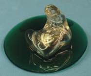
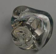
The second thing was having impressions made. This is the beginning of the process of making your in ear, so this is where we begin the photo journal. In order to make a model that precisely fits your ear, they need a cast of your ear to work with. This starts by taking a small piece of foam with string attached and very carefully placing it near your eardrum so the silicone material used to produce a cast cannot adhere to the eardrum itself. If you are a stage musician, they often have you hold a block in your teeth during the process to make sure pressure on both sides of the eardrum is kept even during the curing process. While not entirely necessary for listeners, singers will often see a significant increase in comfort if they are modeled in this fashion. Once the foam dams are positioned, the next step is to fill your ear with a quick drying silicone that hardens to the shape of your ear. During the curing process, you will feel the silicone become dryer and slightly pull away from the ear. This indicates the material is curing and the resultant mould will be slightly smaller than the ear.

In my case, the audiologist at Eartech did my impressions and the cost was part of the price of the monitors. If you do not live close enough to come to the office and have your impressions made, most audiologists offer the service for a fee. Remember to shop around and find an audiologist that does these on a regular basis as the resulting product will only be as good as the mould you send them.
This introduces the first delay in the process. Usually it takes a few days for impressions to find their way from the buyer to the manufacturer. Depending on the carrier and distance, this can be a day or several weeks.

When the impressions arrive at the office, the first step is to clean them up. The silicone is ground to remove any high spots and the strings removed.


Once shaped as above, a silicone putty is used to fill in any crevices left from removing the string or other low spots. This ensures a proper fit and is critical to creating a smooth shell. Once the putty cures, an additional sanding and cleaning step makes sure, all is blended together seamlessly.

One problem the previous step introduces is that now we have a smooth impression that is too small. Grinding and sanding remove enough material that the smoothed model will have a loose fit in the ear.

To fix this, the impressions are dipped in a high melting-point wax to provide a nice smooth surface coat and increase the surface slightly. The wax has to have a melting point high enough that the next steps wont melt the coating back off.
Pretty much all custom IEMs start out the same. It is at the next step where things split into two groups. Old school makers (Including Eartech) use the moulded acrylic method outlined here. Increasingly, other manufacturers are switching to scanning the impression and using a 3d printer to make the shells. Both methods produce usable IEMs but each method has its advantages and drawbacks. The Old school method is slow and labor intensive but makes a very good looking and sounding IEM which is why Eartech has stuck with this method even though they do 3d print some of their hearing aids and have the tooling to 3d print EIMs too should they decide to at some later date. I can see a 3D printer providing a fast way to build universal shells if and when they decide to do so.

The next step is to make the reverse mould from the impression. Agar (Same stuff used for bacterial culture media) is used to create the mould. The Agar must be heated to 190° F in order to liquify and then let cool before use to prevent melting the wax.

Once cooled, a tube slightly larger than the impression is dipped into the liquid agar and sealed to the bench. The impression is placed into the tube and then filled with agar. Now we have the second delay. Depending on conditions, the agar can take anywhere from 20 minutes to an hour to fully cure.

Once fully cured, the impressions are pulled from the agar moulds and we are ready to begin creating the acrylic shell.

The moulds are blown out with compressed air to remove any residual moisture, as a completely dry surface is needed. This is a balancing act as over time moisture will evaporate from agar media and a couple days after casting the mould it will become unusable, as it will have lost enough moisture content to shrink. This can introduce another delay to the process as knowing that the acrylic shell should be done within 24 hours of the mould production for best results means the team has to plan accordingly.
The next step contains a neat trick. Ask yourself, how do you fill that agar mould so that you only get a shell and not a solid object? If you try to pour something fast drying and roll it around you run the risk of gaps, if you simply fill it up, you then have to grind or carve all the excess material out of the shell, which is quite a time investment. Neither sounds like a good plan.

The answer lies in the materials used to make the shell. The Acrylic used is UV cured.

The mould is filled entirely and the top covered with an opaque material so the UV only penetrates from the sides and the bottom of the block. A very short burst of UV is enough to create a hardened shell a couple millimeters thick without curing the center.

Once that burst is completed, the covers are removed and the excess is put back in the bottle for next use.

Before putting the moulds back in the UV for a full cure, a small amount of acrylic is added to the canals so they will be solid when finished.

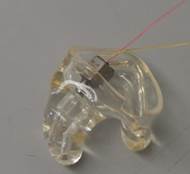
Now the hollow shell is cured for an extended period along with the acrylic for the faceplates.
Over the next few weeks, I spent a little over nine hours with Seth, Richard, and James and came away with a new appreciation for the artisanship required to make a custom in-ear as well as a new set of monitors. I have done a formal review of the Custom Quint iem detailed here in a separate article so will confine this to the build process.
The process starts with the decision to have a custom made instead of buying a universal design. Most of us start with universals as they give us a way to dip a toe in the pond without a long-term commitment. With a universal, if you do not like it, selling it is usually as simple as posting an ad. With a custom, there is a larger commitment. If you decide you do not like it, and want to sell, the cost to re-shell them must be accounted for and usually selling them is more of a challenge. The advantages to a custom are better fit and isolation than universal designs. (As a side benefit, if you have a latex allergy, most tips are latex and a custom that does not require a tip to seal can be a godsend). After having fought with tips and comfort in a large number of monitors, I decided it was time to see what a custom could really offer.
The first time I went to their office, I did two things. The first was listen to the demo models they had available to determine which model I was going to purchase. I highly recommend you take music you are intimately familiar with and your own choice of DAP and amp so you know how the in ear is going to sound with your gear. Since we are working with all BA drivers with tubes running from the driver to the nozzle, the shape and size of the housing has very minimal (if any) impact on sound so the universal demos work well as long as you do your part and listen for long enough to really make a solid choice. I would suggest 20-30 minutes per model is a realistic minimum to have an idea of what you are getting and longer is better. I had 6 tracks I was using to test the two models I had decided I was most interested in initially and briefly auditioned two others just to make sure my initial thoughts were correct about which I would prefer.
The second thing was having impressions made. This is the beginning of the process of making your in ear, so this is where we begin the photo journal. In order to make a model that precisely fits your ear, they need a cast of your ear to work with. This starts by taking a small piece of foam with string attached and very carefully placing it near your eardrum so the silicone material used to produce a cast cannot adhere to the eardrum itself. If you are a stage musician, they often have you hold a block in your teeth during the process to make sure pressure on both sides of the eardrum is kept even during the curing process. While not entirely necessary for listeners, singers will often see a significant increase in comfort if they are modeled in this fashion. Once the foam dams are positioned, the next step is to fill your ear with a quick drying silicone that hardens to the shape of your ear. During the curing process, you will feel the silicone become dryer and slightly pull away from the ear. This indicates the material is curing and the resultant mould will be slightly smaller than the ear.
In my case, the audiologist at Eartech did my impressions and the cost was part of the price of the monitors. If you do not live close enough to come to the office and have your impressions made, most audiologists offer the service for a fee. Remember to shop around and find an audiologist that does these on a regular basis as the resulting product will only be as good as the mould you send them.
This introduces the first delay in the process. Usually it takes a few days for impressions to find their way from the buyer to the manufacturer. Depending on the carrier and distance, this can be a day or several weeks.
When the impressions arrive at the office, the first step is to clean them up. The silicone is ground to remove any high spots and the strings removed.
Once shaped as above, a silicone putty is used to fill in any crevices left from removing the string or other low spots. This ensures a proper fit and is critical to creating a smooth shell. Once the putty cures, an additional sanding and cleaning step makes sure, all is blended together seamlessly.
One problem the previous step introduces is that now we have a smooth impression that is too small. Grinding and sanding remove enough material that the smoothed model will have a loose fit in the ear.
To fix this, the impressions are dipped in a high melting-point wax to provide a nice smooth surface coat and increase the surface slightly. The wax has to have a melting point high enough that the next steps wont melt the coating back off.
Pretty much all custom IEMs start out the same. It is at the next step where things split into two groups. Old school makers (Including Eartech) use the moulded acrylic method outlined here. Increasingly, other manufacturers are switching to scanning the impression and using a 3d printer to make the shells. Both methods produce usable IEMs but each method has its advantages and drawbacks. The Old school method is slow and labor intensive but makes a very good looking and sounding IEM which is why Eartech has stuck with this method even though they do 3d print some of their hearing aids and have the tooling to 3d print EIMs too should they decide to at some later date. I can see a 3D printer providing a fast way to build universal shells if and when they decide to do so.
The next step is to make the reverse mould from the impression. Agar (Same stuff used for bacterial culture media) is used to create the mould. The Agar must be heated to 190° F in order to liquify and then let cool before use to prevent melting the wax.
Once cooled, a tube slightly larger than the impression is dipped into the liquid agar and sealed to the bench. The impression is placed into the tube and then filled with agar. Now we have the second delay. Depending on conditions, the agar can take anywhere from 20 minutes to an hour to fully cure.
Once fully cured, the impressions are pulled from the agar moulds and we are ready to begin creating the acrylic shell.
The moulds are blown out with compressed air to remove any residual moisture, as a completely dry surface is needed. This is a balancing act as over time moisture will evaporate from agar media and a couple days after casting the mould it will become unusable, as it will have lost enough moisture content to shrink. This can introduce another delay to the process as knowing that the acrylic shell should be done within 24 hours of the mould production for best results means the team has to plan accordingly.
The next step contains a neat trick. Ask yourself, how do you fill that agar mould so that you only get a shell and not a solid object? If you try to pour something fast drying and roll it around you run the risk of gaps, if you simply fill it up, you then have to grind or carve all the excess material out of the shell, which is quite a time investment. Neither sounds like a good plan.
The answer lies in the materials used to make the shell. The Acrylic used is UV cured.
The mould is filled entirely and the top covered with an opaque material so the UV only penetrates from the sides and the bottom of the block. A very short burst of UV is enough to create a hardened shell a couple millimeters thick without curing the center.
Once that burst is completed, the covers are removed and the excess is put back in the bottle for next use.
Before putting the moulds back in the UV for a full cure, a small amount of acrylic is added to the canals so they will be solid when finished.
Now the hollow shell is cured for an extended period along with the acrylic for the faceplates.
Last edited:


