kkugel
Member of the Trade: IEM Maker
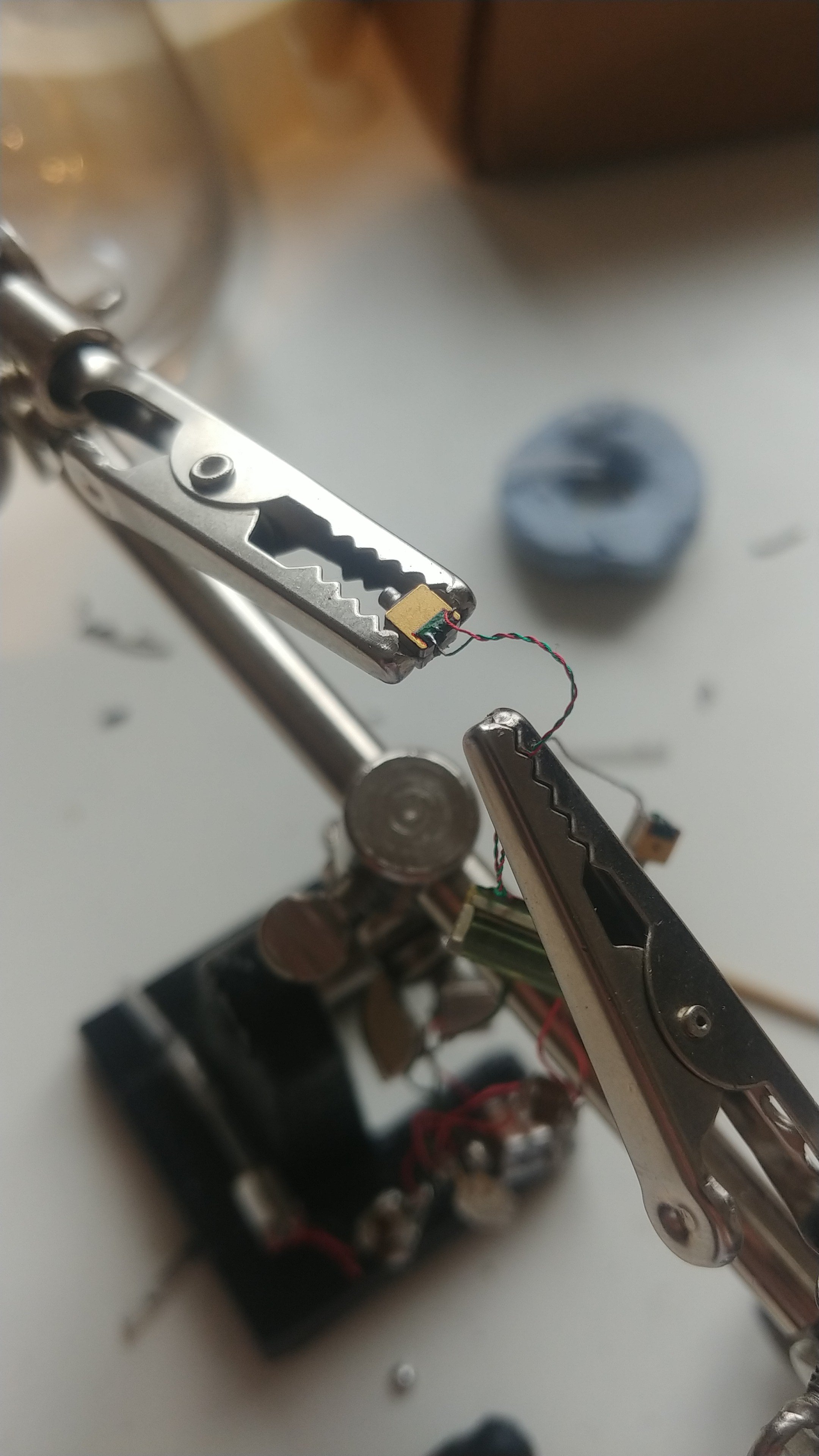
Guys if you use EST...tape the cables to the drivers STRONG! I teared them off and had to resolder the smallest connection ever...


ghademn, man. this gives me anxiety. I never use alligator clips with my drivers. If you must do, wrap them with heat shrink so it won't dent the drivers. better yet, use blu tack or tack it.Guys if you use EST...tape the cables to the drivers STRONG! I teared them off and had to resolder the smallest connection ever...

 ) I also second being really careful with the ESTs. Good thing that I think I have spent a lot of time soldering in my life that I don't find it troublesome anymore to resolder this. But I did lift a pad off when I accidentally tugged the wire. That was not a good day to say the least.
 Haha I've not noticed any denting or change in FR, the clamp force is not so high. I use a Hakko FX-888D soldering station on 480 C and this soldering holder with CFH electronic solder wire.ghademn, man. this gives me anxiety. I never use alligator clips with my drivers. If you must do, wrap them with heat shrink so it won't dent the drivers. better yet, use blu tack or tack it.) I also second being really careful with the ESTs. Good thing that I think I have spent a lot of time soldering in my life that I don't find it troublesome anymore to resolder this. But I did lift a pad off when I accidentally tugged the wire. That was not a good day to say the least.
May I ask your soldering setup?
Drivers took it fine so far, 480 was genius today, was able to solder EST driver pads in like 0.3 seconds haha, no big heat transfer to driver at allYour 480*C makes me wonder about its high temperature. I always use 320*C. No flux, well pretinned litz.

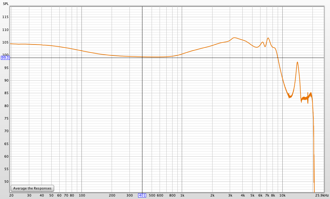
Here's the best FR we achieved without EST Dhruv is talking about, it sounds like ass and as if singers are glued to their instruments, really smeared and congested all over the place, mids are sometimes even a single blob of sound, especially for electric guitar rock music. Worse than a KZ ATE to be honest, which is kind of unbelievable. I always measured the same amount of bass and it continues down to 6 Hz linear. However somewhere along the deep rumbling got lost and the bass texture too. I exchanged drivers too for the ones of the other channel, exact same graph and sound.

CSD?What's the CSD like?
X and Y axis are the frequency graph in CSDP.s. - can someone briefly describe how to interpret a waterfall graph? What's good, what's bad, what can you glean from it, similar to a frequency response graph - can't tell the whole story, but what clues can it give you?

