chum_2000_uk
100+ Head-Fier
- Joined
- Jan 5, 2009
- Posts
- 208
- Likes
- 10
Hi guys,
I've just bought a PSU board and R-core transformer from Kingwa at Audio-GD to power a Jaycar headphone amp kit that I am in the middle of building. I'm not quite 100% sure on how the r-core is wired to the PSU, so if anyone could help me out a little that would be great

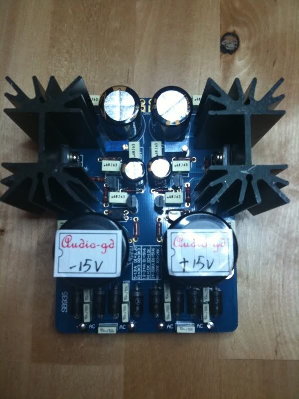
Here are pics of the PSU and R-core:
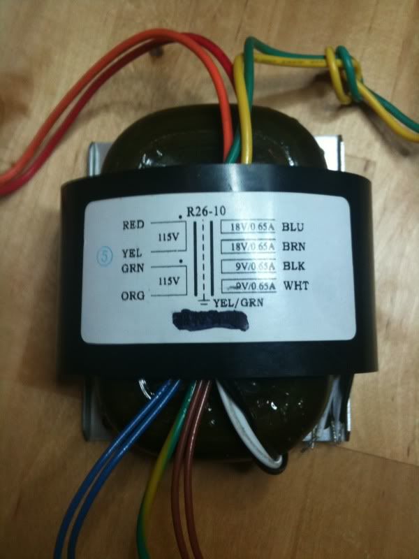
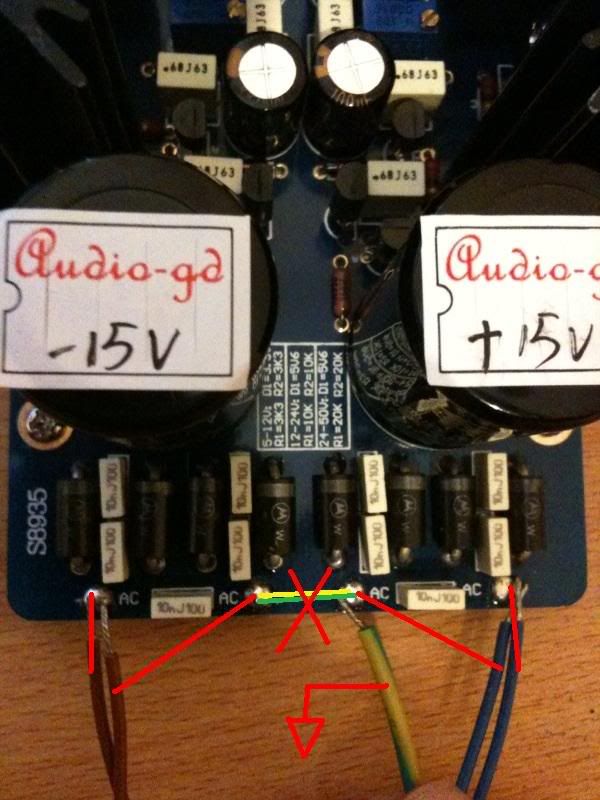
As you can likely tell from my user name I am based in the UK, so I need 230V. Kingwa at Audio-GD already soldered the yellow and green wires together for me for the primary so that is sorted. Its just the secondary that I am unsure about, because as you can see for 18-0-18V it says to use blue and brown.
If you look at the A-GD PSU, it has 4 AC solder points at the bottom, and as I see it there are 5 wires to connect to these; 2 blue, 2 brown and the green/yellow ground wire seen between them in the pic.
So.... I'm thinking that they need to be soldered like this:
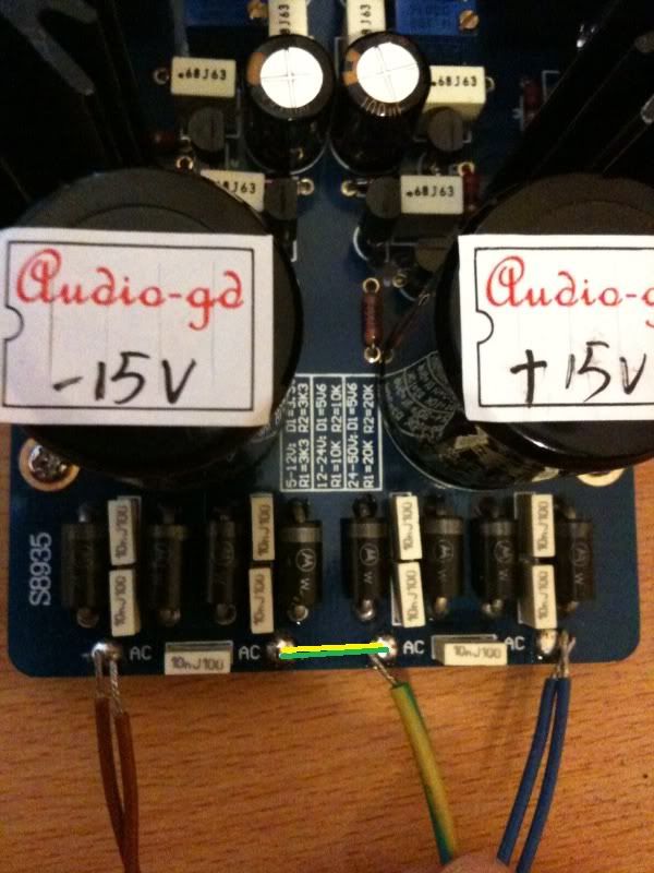
both brown to one solder point, both blue to another, then the green/yellow wire to one of the inner solder points, and a common ground wire across to the other inner solder point. That's my thoughts on how the secondary should be wired, any input will be so much appreciated.
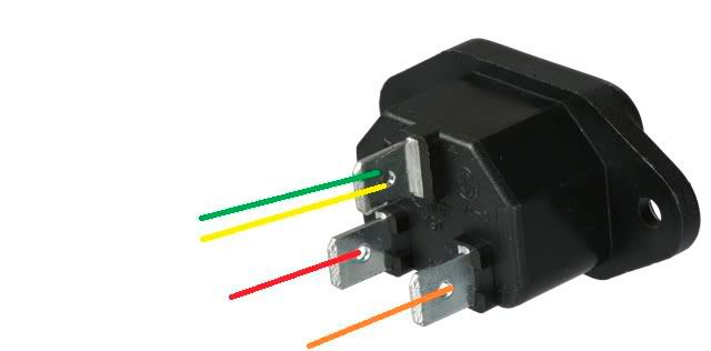
Ok, while I'm here... I may as well make sure that my understanding of the primary wiring is correct too (this will be the first time I have wired a transformer up). While testing at least, I am probably going to wire the primary up to a switched IEC inlet, like this:
Bulgin | Connectors | Electrical/Power | IEC Connectivity | |BZM27/Z000/53B
So I assume the red and orange go to live and neutral (does it matter which goes to which, is either way fine?) and the centre tapped yellow and green wires go to earth, correct?
And with that connector that I have linked to above, I assume the switch will already be pre-wired to the IEC socket, so WONT have to be wired separately?
Sorry for the lengthy post, I just want to make sure I know exactly what I am doing before I start. Thanks so much for your help

I've just bought a PSU board and R-core transformer from Kingwa at Audio-GD to power a Jaycar headphone amp kit that I am in the middle of building. I'm not quite 100% sure on how the r-core is wired to the PSU, so if anyone could help me out a little that would be great
Here are pics of the PSU and R-core:
As you can likely tell from my user name I am based in the UK, so I need 230V. Kingwa at Audio-GD already soldered the yellow and green wires together for me for the primary so that is sorted. Its just the secondary that I am unsure about, because as you can see for 18-0-18V it says to use blue and brown.
If you look at the A-GD PSU, it has 4 AC solder points at the bottom, and as I see it there are 5 wires to connect to these; 2 blue, 2 brown and the green/yellow ground wire seen between them in the pic.
So.... I'm thinking that they need to be soldered like this:
both brown to one solder point, both blue to another, then the green/yellow wire to one of the inner solder points, and a common ground wire across to the other inner solder point. That's my thoughts on how the secondary should be wired, any input will be so much appreciated.
Ok, while I'm here... I may as well make sure that my understanding of the primary wiring is correct too (this will be the first time I have wired a transformer up). While testing at least, I am probably going to wire the primary up to a switched IEC inlet, like this:
Bulgin | Connectors | Electrical/Power | IEC Connectivity | |BZM27/Z000/53B
So I assume the red and orange go to live and neutral (does it matter which goes to which, is either way fine?) and the centre tapped yellow and green wires go to earth, correct?
And with that connector that I have linked to above, I assume the switch will already be pre-wired to the IEC socket, so WONT have to be wired separately?
Sorry for the lengthy post, I just want to make sure I know exactly what I am doing before I start. Thanks so much for your help