Help wiring R-core and Audio-GD PSU

Apr 12, 2010 at 5:38 PM Post #31 of 40
You can use 4 diodes but this works just as well (or any of the dozens and dozens of similar components). I did something similar in the ESX amp I built (there is a link in my signature) but there I incorporated a voltage divider since the rectified voltage was too high.
 
Apr 14, 2010 at 2:57 PM Post #32 of 40
Hi guys, I had a go at designing the layout of the case yesterday evening, here is what I came up with:

IMG_0091.jpg


Sorry about the shabby drawing, I couldn't be bothered to try and do it on a computer package as it would have taken me ages most likely! Not sure if this is going to be the final layout, but it was the best I could do last night - went through a few different layouts, but I found the Jaycar amp to be quite strange orientation wise - not easy to fit in to the shape of case I want to get without crossing power and signal cables. There were one or two things I wasn't 100% sure of in respect to how they actually wire up, particularly the DPDT LED switch that I want to mount to the front panel as the on-off switch.

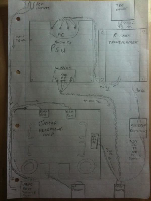
Anyway, I'll run through input and output signals first, then I'll run through all the power stuff. Oh before I do that, I should mention that this is pretty much to scale and as it goes the usable space inside the case is near enough the same size as a piece of A4 paper.

So top left, which is obviously the back panel, we have the chassis mount RCA inputs. The input signal wires run all the way down the left side of the case to the Alps RK27 volume pot at the bottom left (front panel, left). Then back out from the volume pot, the signal wires run up to the Jaycar amp board RCA input sockets. As you can hopefully see the Jaycar Headphone amp board is kind of bottom left of the drawing, so towards the front left in the case.

The Headphone (HP) socket is bottom middle, which will wire straight to the HP outputs from the amp board and mount on the middle of the front panel.

Now for power. Top right we have the IEC inlet for mains, which is DPST switched and fused. Just underneath is the R-Core transformer, with the 240V AC wires running from the IEC to the R-Core to provide power to it's primary windings. To the left of the R-Core is the Audio GD PSU board, oriented with the 18-0-18V AC inputs at the top, and the +/-15V DC outputs at the bottom. So I have the 18V AC secondary winding wires running left, out from the R-Core to the top of the PSU board.

The +/-15V DC supply wires run from the bottom of the A-GD PSU, down and right to the very bottom right where the LED illuminated DPDT latching switch is. Then the 15V DC wires run back out from the DPDT switch, back up and left to the +/-15V DC power connector of the amp board. So I'm hoping that running it that way will allow me to basically turn the amp board on and off. Let me know your thoughts on this, because I was thinking this through, and if I do it this way then the transformer and PSU will still be turned on even though the amp board is turned off right? Maybe this isn't a good way to do it? Obviously though I do still have the IEC switch on the back panel too, that does turn everything completely off.

Right, nearly there now! The illumination LED for the DPDT switch uses a separate circuit, and requires 12V DC. So I am going to make a bridge rectifier board with smoothing capacitor as Spritzer suggested, to turn one of the 9V AC windings from the transformer into around 11 odd Volts DC. The rectifier board can be seen at the right, with 9V AC wires from the R-core going into it, and 11.5V DC wires going to the switch.

Think that's it!!!

Let me know your thoughts on the layout if you can guys, I'm sure there are things I haven't considered, and in all likelihood a better way to lay this out! I'm particularly interested in peoples thoughts on the front DPDT switch and what part of the power supply this should be switching.

Thanks so much for any help guys!
 
Apr 14, 2010 at 7:19 PM Post #33 of 40
That layout looks just fine and you shouldn't have any noise issues. I do think it would be a good idea to use the front mounted switch to switch the wall AC voltage rather then the PSU as I don't know how that design will like being powered up for a long time without a load present. With the switch just switching the DC voltage then the LED would also be lit all the time and would not function as a power indicator.

The switch should be clearly marked as to what connection is what but a simple ohm meter can also help you to figure that stuff out.

I've built an amp in that same chassis and here you can see how I kept the input wiring well away from everything. This amp is built upside down though but it is 100% hum free which is pretty surprising given the hungry tubes it uses.

 
Apr 15, 2010 at 12:07 AM Post #34 of 40
Thanks again Spritzer, as always you have been a great help. I will do as you suggest and have the front switch also switching the 240V on and off. I'll probably flip the transformer the other way around in this case so the 18V AC can go straight across to the relevant AC inputs of the PSU, and the 240V r-core input wires can pick up the front switch's output. I'll run the 240V down the right of the case, along with the 9V AC until the rectifier, where the 9V AC can run into the rectifier and the 240V can run past and down to the switch input.

Thanks for the suggestion! It definitely makes more sense to do it this way, and as you say the led will be an indication of power then too, instead of being on permanently!

Cheers!

The only thing I'm not sure about now is how and where to run chassis earth wires... But I'll ask about that when I get the case if that's ok, as it will be easier to visualise it all. Thanks so much!
 
Apr 15, 2010 at 8:01 AM Post #35 of 40
When grounding something like this, drill a hole in some panel and put a screw through it. Now clear off all paint/anodized finish underneath the screw so it has a direct contact with bare metal. Now you attach two wires to the screw (via those crimp on connectors), one from the earth tab on the iec input and the other that connects to the amps ground.

As for grounding the amp, star grounding is the best way to do it. By that I mean all the grounds are connected to one point on lets say, the amp board. Ground from the PSU, earth from the chassis and the input ground from the volume control all connect there to have as little potential as possible.
 
May 7, 2010 at 3:11 PM Post #36 of 40
Hi again guys, the past couple of evenings I've been trying to get the amp working in the case. I tried grounding it like you said Spritzer, but for some reason the IEC inlet fuse keeps blowing when I have the IEC earth bolted to the chassis ground. I drilled a hole and scraped off the paint like you told me to etc etc.
 
Any idea why that fuse is blowing when I have the IEC earth connected to chassis ground? Basically as soon as I turn the power there is a buzz and the fuse blows straight away!
 
Cheers for any help guys 
 
May 7, 2010 at 5:23 PM Post #37 of 40
Either the fuse is too small or something is causing the system to draw too much current.  The grounding should have no effect on this as if there is any live voltage on there, the breaker for the house will cut off all power.  What fuse are you using? 
 
Apr 23, 2016 at 2:25 PM Post #38 of 40
All,
 
Newbie to this site as well as DIY audio.   I bought a DAC board ( below is the link ) from ebay recently and trying to provide power supply to this.  The board requires a 15v-0-15v and 0-9v input. It is my understanding that i need a R-Core transformer in order to accomplish this.  Below is the R-core I found on ebay and I was hoping the gurus out there can help me in :
 
1. Confirming the transformer I found will work for what I need to do
    http://www.ebay.com/itm/115V-230V-30W-High-Quality-Audio-R-Core-Transformer-15V-15V-9V-9V-For-Preamp-/171364852060?hash=item27e624215c:g:PfgAAOSwBadTpmyy
2. Confirming the wiring aspects 
3. I intend to buy an IEC Socket with Switch. Any specification I should follow ?
4. Fuse. Should I think about adding one for safety ? 
 
Any help will be much appreciated.
 
Link for the DAC Board  : http://www.ebay.com/itm/24bit192K-CS8416-WM8741-OPA2134PA-audio-decoder-completed-board-/121939117379?hash=item1c64234543:g:sKcAAOSwI3RW-h9N
 
Eventually I plan on getting a nice case for the DAC as well.
 
I dont think I can attach pictures since im a new member but on the side of the board I see two power terminals. One reads 15v-0-15v (3 holes/terminals) and the other 9V ( 2 holes/terminals)
 
 
Thanks
RS Thomas
 
May 10, 2016 at 11:37 AM Post #40 of 40
Thanks.  I used the guideline and help on this thread.  Put everything together.  Sound is good more on the bright side, but it could be due to the burn in period?.  I have also noticed that playing a CD from my CD player and routing through this external DAC using optical cable, the volume drops significantly. Is this normal ? or is that due to the burn in period as well ?   Anything I can do to improve the volume level ?
 
Thanks
 

Users who are viewing this thread

Back
Top