I want to solder a cable to a 3.5 mm Viablue plug and have 4 wires.
The wires were origianlly soldered to a 2.5 mm balanced plug. It's for a IEM that have 2 pin connectors.
Where do I solder the wires to and does it matter which one goes to which part of the plug?
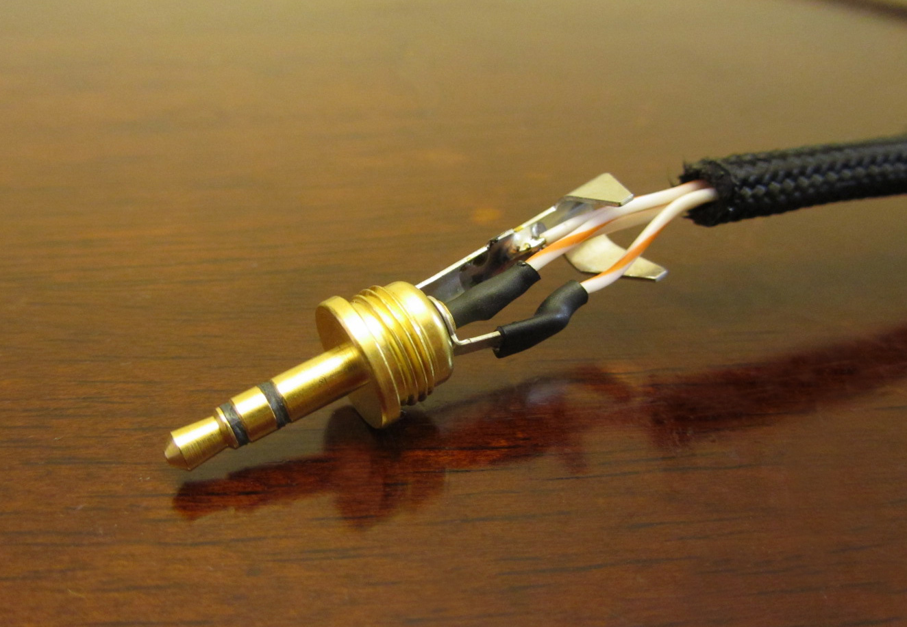
Here a picture
Paladin covered most of I would have said, so I will just add a few words of wisdom.
1) TRS = Tip, Ring, Sleeve. The easy way to remember what these are is that the sleeve is alway the common (or ground) and Ring = Right (R=R). This only works for TRS plugs.
2) Don't solder anything to the cylindrical part of the plug that gets inserted into the jack
")
The sleeve part that you will connect the two common ground wires to has a hole, which is really nice. Many plugs don't have a hole for the sleeve. The Tip and Ring will be harder. Your best bet is to use a vise or helping hands clips (vice is more better) to hold the plug as you solder. Tin the wires. There are plenty of YouTube videos on tinning, if you don't know how. Add a little tiny solder to the plug's tip connector, then pull back a sec. touch the tip wire to the tip connector, then apply the iron to fuse the wire to the connector. That may only take a second or two. let it cool for 15-30 seconds, then do the same on the ring connector.
You might even want to slide a 1/4" of very thin heat shrink on to the tip wire BEFORE you solder it, then after you solder it, slide the heatshring down and cover the exposed wire and connector. If you are slick, you could do the same wit the ring solder joint too, but obviously you need some thicker heat shrink. That will server as a little extra adhesive and some electrical insolation. The heat shrink is not required; it's only nice. Sort of an example I stole from the interwebs that shows some heatshrink:
I'm not sure how the plug provides strain relief since there is no crimp. If there is no strain relief, you may need to hot glue the wires in place or something. I think it might have a screw that's supposed to lock the wire in. If that is the case, you might want to ticket/protect the wire where the screw's goes with the heat shrink.
Personally, I think you've selected one of the more difficult plugs to solder. It's always easier when you have actual solder lugs. Be REALLY careful not to overhear that central column, or you will melt it and ruin the plug.
Hope this help.