00940
Headphoneus Supremus
- Joined
- Nov 6, 2002
- Posts
- 4,493
- Likes
- 47
Quote:
You're right. This cfp thing goes completly crazy at high frequencies. I've tried a few transistors in ltspice and nothing changes much.

This being said... The digital filter inside the pcm1798 achieves a 120dB attenuation at 4fs. For 44.1KHz, wouldn't it mean that there isn't too much junk at 2MHz ?
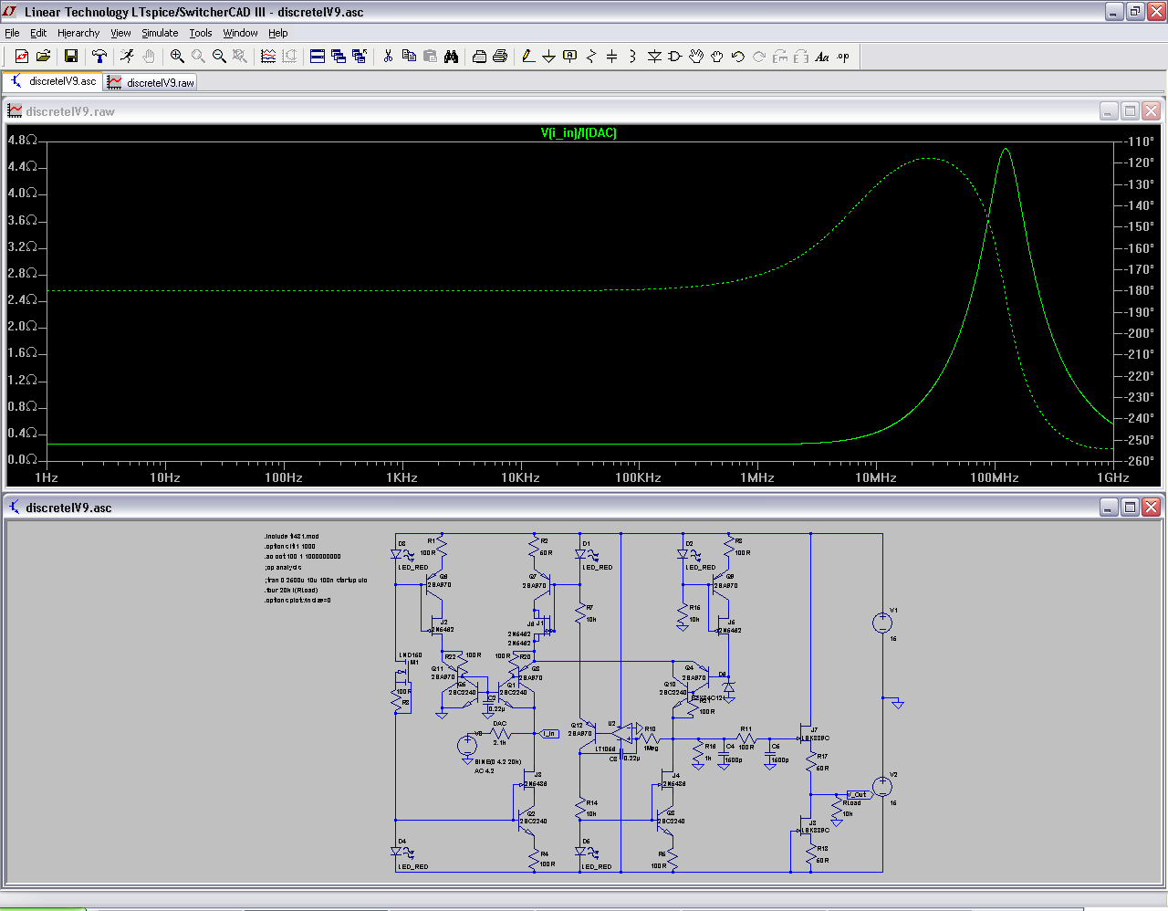
Here's what I'm having right now in ltspice:

| Originally Posted by cetoole /img/forum/go_quote.gif Yeah, up to about 2MHz. Havnt been able to keep it from going inductive above that, except by adding capacitance to the input, which will increase distortion. Maybe with different transistors than I have tried it would work nicely. |
You're right. This cfp thing goes completly crazy at high frequencies. I've tried a few transistors in ltspice and nothing changes much.
This being said... The digital filter inside the pcm1798 achieves a 120dB attenuation at 4fs. For 44.1KHz, wouldn't it mean that there isn't too much junk at 2MHz ?
Here's what I'm having right now in ltspice: