Part 6 – Filter Design in ADCs and DACs
How do the digital audio filters discussed in Part 5 work, and how should they be designed? This may sound counterintuitive, but the filtering required in both ADCs and DACs is actually very similar.
In an ADC, the audio is coming into the converter at a higher rate than we want to output – typically by a power of 2. To deal with this, the converter must remove content above the Nyquist frequency, which allows it to drop samples (allowing it to lower the sample rate from 88.2k to 44.1k for example) without content from above the Nyquist frequency aliasing down below it. This is handled in Digital Signal Processing by way of low-pass filtering.
In an oversampling DAC, audio is coming in at a lower rate than we want to feed to the converter. There are several approaches for how to tackle this issue, but by far the most effective is to insert samples with an amplitude of zero between the actual audio samples to increase the sample rate, then low-pass filter the signal to remove the Nyquist images this process creates. Once again, DSP is used to implement low-pass filtering.
How is this digital low-pass filtering carried out? In simplified terms, the digital audio signal is run through a series of ‘coefficients’ – multipliers which change the amplitude of the audio sample by an amount, defined by a number between 0 (no output) and 1 (the original full amplitude of the sample). Each of these coefficients is what is referred to as a ‘tap’. A higher number of taps means the signal is run through a larger amount of coefficients in the filter. The output of the filter at any one point is the sum of all of these coefficients multiplied by the respective samples.
Audio websites and magazines often feature ‘impulse response’ plots of filters in audio products. These typically show the output from a filter when it is given samples, all with an amplitude of zero, then a single full-scale (all 1s) sample, then all zero samples again. The effect of this is to show the coefficients in a filter, which define how the filter works. Typically, this filter is a derivative of what is known as the ‘sinc’ function. The sinc function is defined as sin(x)/x and looks a little like the below graph.

There are several useful properties of the sinc function – it acts as an ideal low pass filter (the set of coefficients used in a digital filter, as previously described, are taken from this function, hence the Y axis being shown as ≤1, which will be shown below); it is mirrored in time in both directions (before and after the impulse, the single full-scale sample shown in the middle of the above sinc graph) and it offers the same delay at all frequencies (not all filters do this). An analogue filter will delay some frequencies more than others, creating phase issues. Filters which offer the same delay at all frequencies are referred to as phase linear.
Given these factors, the sinc function can be manipulated to provide the desired frequency response. The three main factors that can be adjusted with digital filters are:
- The -6dB point – the frequency at which the filter reaches 6dB of attenuation.
- The filter length – the number of coefficients used in the filter, with one coefficient often being referred to as a ‘tap’.
- The windowing technique – this is linked to both of the above factors (this is a simplified explanation).
Cutoff Frequency (-6dB Point)
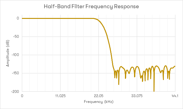
To explore the factor of the cutoff frequency of a filter, take the below graph, which shows the most commonly used digital filter. This is a ‘half-band’ or ‘Nyquist’ filter, with coefficients based off of the sinc function. This filter is designed in such a way that the -6dB point is at the Nyquist frequency of our target. For a low-pass filter in, for example, an ADC, the Nyquist frequency is set at 22.05kHz. For a tap length of 128, this generates the below impulse response.

The crucial aspect of this filter is that every other coefficient (the data points on the graph marked by an X) is 0 – which makes it twice as computationally effective as a non-Nyquist filter (as using a coefficient of 0 always results in an output of 0). The drawback to this type of filter is that by definition it only reaches 6dB attenuation at the Nyquist frequency. Thus, aliasing artifacts from the ADC which will be mirrored down to below Nyquist frequency will not be correctly attenuated. We would therefore ideally want the -6dB point to be
below the Nyquist frequency, to remove said aliases and to maintain good attenuation at the Nyquist frequency.
Windowing Technique
There are some drawbacks to using the sinc function as the basis for a digital filter – firstly, the filter would be infinitely long (due to the sinc function being a mathematical function with no defined length), which is problematic in the real world. It also requires data from the future, as the filter coefficients include data from
before the current sample being played. So how should these issues be addressed?
A good start would be to define the filter as
not infinitely long. Doing so would allow the incoming audio signal to be buffered by a certain number of samples. This means the filter can then effectively have some data from the ‘future’ by delaying the entire audio signal by that amount of samples.
However, defining the filter with a finite length leads to some mathematical problems – the sinc function starts to get very small when moving further away from the central impulse, but not so small that the function becomes irrelevant. Sinc is infinitely long, but it is unwise to simply select a finite section of the sinc function to use as the basis for a filter, chopping off the ‘start’ and ‘end’ of the function to create a finite length. Doing so actually causes the resultant filter to not work very well. The below graph shows an example of a digital low-pass filter designed to work for CD rate audio, with a tap-length of 64 taps, where the ends of the sinc function have simply been chopped off to provide the coefficients used in the filter.

As can be seen from this graph, this filter does not provide a good response. The stop-band rejection above 22.05kHz is poor, and there is a significant ripple in the passband (below 22.05kHz). This problem is best addressed through a technique called ‘windowing’. This involves taking the coefficients for the filter we want to use, such as a finite section of the sinc function, and then multiplying them by another set of coefficients to reduce the negative effects seen above.
There are many approaches to windowing (different sets of functions / coefficients) used, but for this example, a raised cosine window will be used.
This diagram shows an example of a Raised Cosine window.
Applying this window to the above 64-tap filter results in the below frequency response:
As can be seen, this provides drastically better results. The stopband has far better rejection and the rippling seen in the passband is no longer present. What this means is that when designing a filter for use in audio, the windowing function needs to be selected carefully for correct filter performance.
Filter Length
The third factor to consider with filter design is the length of the filter itself. As previously discussed, we need to filter the output of a DAC to prevent imaging. This filter needs to be a finite length – longer than nothing but not infinitely long. If this is not done and no filtering is carried out to the DAC’s output, and the samples are played back as they come in, the result is not ideal:
This graph shows the frequency response of a Non-Oversampling (NOS) DAC with no filter on the output.
As discussed in the previous article, a filter for 44.1k digital audio should not affect signals below 22.05kHz, but should heavily attenuate them above this. With no filter in place, not only is there very little attenuation above 22.05kHz (thus leading to lots of false high frequency components), we are also affecting the signal we are interested in: the frequency response at 20kHz is -3dB.
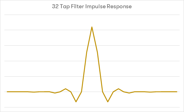
So, how long should the finite length filter on the DAC output be? To illustrate this factor, the same previously mentioned Nyquist filter with a raised cosine window will be used. Firstly, a 32 tap filter:
As can be seen from the above graphs, the frequency response is still far too droopy to be appropriate for use – at 20kHz, the response is still down about 2.8dB. Attenuation for images above 33kHz (or for images in the region of 0-11kHz) are 50dB down. The transition band width is in the region of 20kHz.
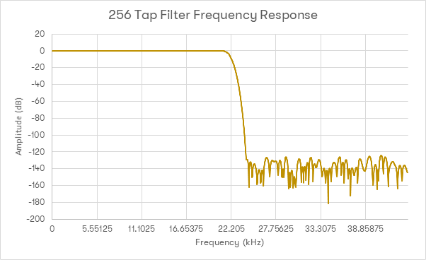
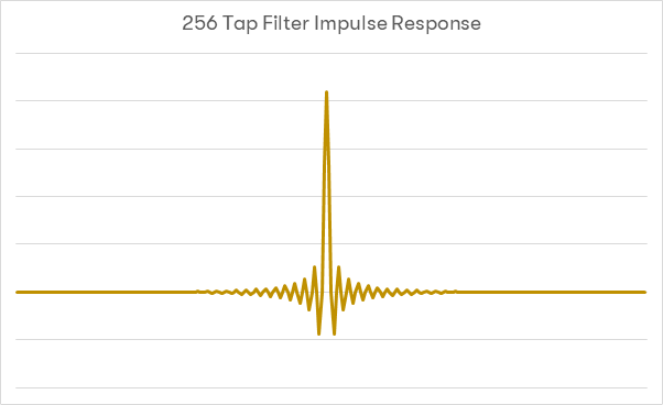
Next, the same Nyquist filter with a raised cosine window will be used, but this time with a length of 256 taps:
This response is visibly much better. The pass-band response is very flat up to 20kHz, and the transition band is approximately 4kHz wide. Images above 22.05kHz are supressed nicely. Looking at the impulse response however, it can be noted that much more data from
before the current sample is playing is required. As such, a larger number of samples from ‘the future’ are required for this filter and will subsequently be having an impact on the current sample, and more samples from ‘the present’ will have an impact later on.
Lastly, using the same example upped to 1024 taps:
As can be seen here, lengthening the filter has a few effects. Firstly, the transition band has become much narrower, so there is less out of band energy. There are, however, some negative effects – because there are more coefficients performing more multiplies, the stopband noise rejection is actually starting to degrade. Noise is beginning to accumulate in the stop-band (which can be partly compensated for with the windowing). There are also now a large amount of samples from the ‘future’ being used (in this example of 2014 taps at 44.1k, around 11mS worth) and an equal amount will be affected in the ‘past’. The effects of these factors are debatable, but
where these samples come from has to be considered. With that in mind, a good real-world example…
dCS 904 – 44.1k, Filter 1
This graph shows the frequency response of the dCS 904 running at 44.1kS/s using Filter 1.
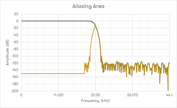
This graph shows the filter frequency response from a very capable ADC, used in many recordings – a dCS 904. The first thing to note about this example is that it
doesn’t use a Nyquist filter like the examples above. The attenuation by the Nyquist frequency is 20dB. This is important as an ADC, by definition, deals with signals that are not bandlimited. The final filter is around 100 taps long, meaning that effectively there is little to be gained from using a much longer filter on replay (inside the DAC). Considering what this response means, the following chart is helpful:
This graph helps to illustrate the area of uncertainty caused by this filter. In the intersecting area, it isn’t possible to differentiate between real signal and an alias. As such, use of excessively long filters here leads to heavy use of DSP to preproduce what is effectively the transition band of the ADC – signal which is undesirable, and unknown.
What this stands to show is that with digital filter design, the signal chain as a whole needs to be considered, as opposed to just the DAC in isolation. DAC filters which are likely to work well with realistic ADC filters are ideal – in reality the use of a filter which is either not present, too short or too long in a DAC can have detrimental effects. Filter length of course must be balanced with the other factors described above, which is where good engineering comes into play – understanding how to employ the necessary trade-offs to create a set of filters which work well regardless of what content is thrown at it. This is the reason a dCS DAC has so many filters to choose from – the DAC doesn’t (and can’t) know the filters which were used to create the signal, so several options allow the user to achieve the best musical experience irrespective of source material.
dCS’s experience with both ADCs and DACs leaves us in a very strong position to be able to create DAC filters which consistently perform to the highest standards, both in testing and with real-world musical signals.


")
