


hakuzen
Headphoneus Supremus
- Joined
- Feb 9, 2016
- Posts
- 1,806
- Likes
- 2,682
i think @castleofargh refers to these pin holes at the base of the coupler. they were called as "pressure equalizing holes" at the coupler's diagram ("h" at following pic).
A real 711 has 2 volumes connected by slits to the main coupler volume. Not sure what you guys talked about.


about impedance/phase measurement, got time ago a box with 3 3.5mm sockets, a switch (to toggle between channels), and a resistor of 100ohm soldered to the right connectors of the socket.
it's very comfortable to use, and minimize leads resistance.

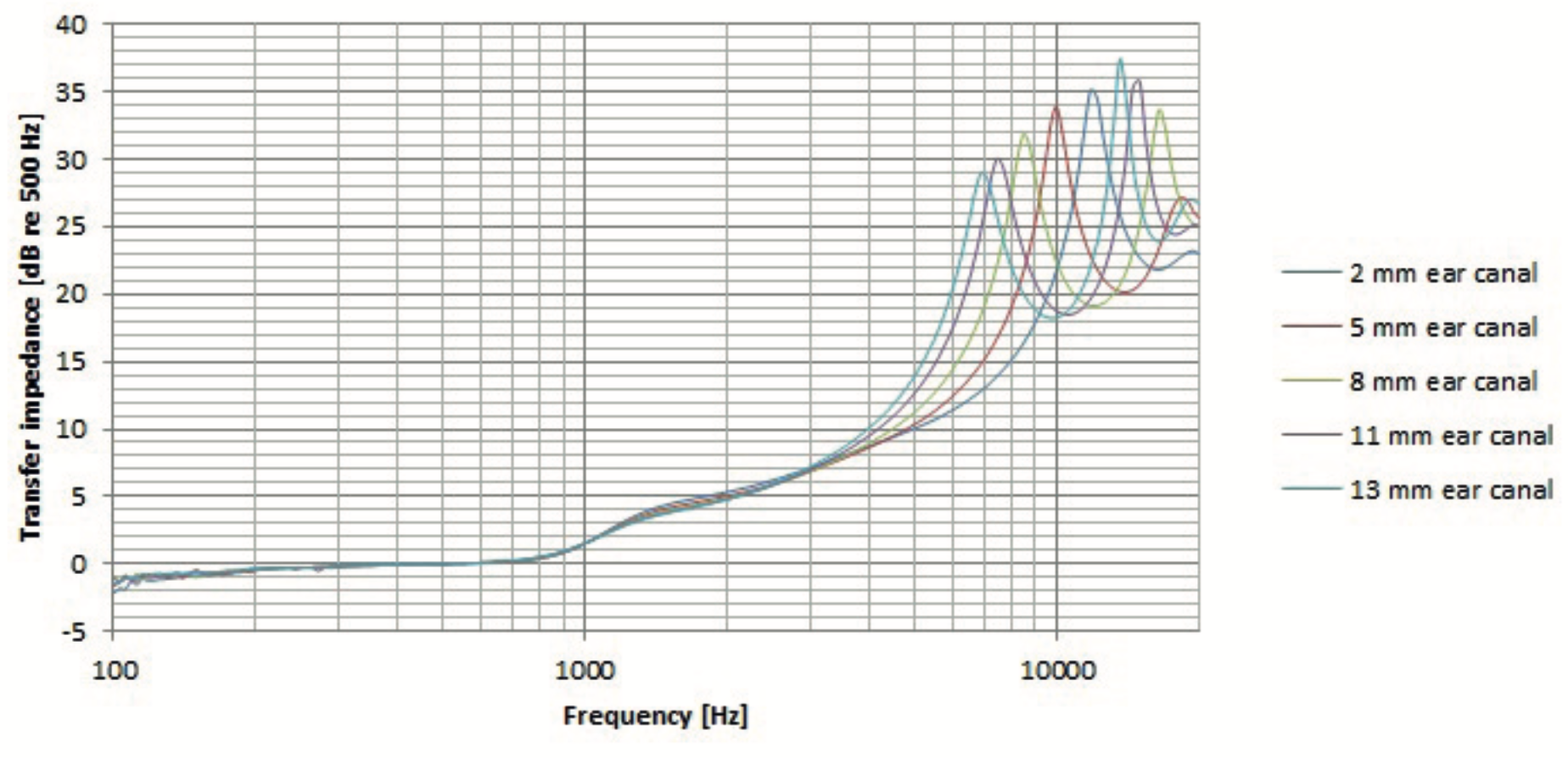
in a 711 coupler, the distance from the mic to the top of the coupler (top of the tip cavity) seems to be 2.55mm, so the BA(s) nozzle of the iem should be located right there. this is my goal when trying to find the right insertion depth for different iem and different tips now.
about SPL measuring, the coupler is also very useful to match desired level. but the attachment requires a 1/2" threaded cap of the meter, or mcgyver tricks to fit it, no leaking:


")


