


MikeW
Headphoneus Supremus
- Joined
- Nov 4, 2005
- Posts
- 1,789
- Likes
- 243
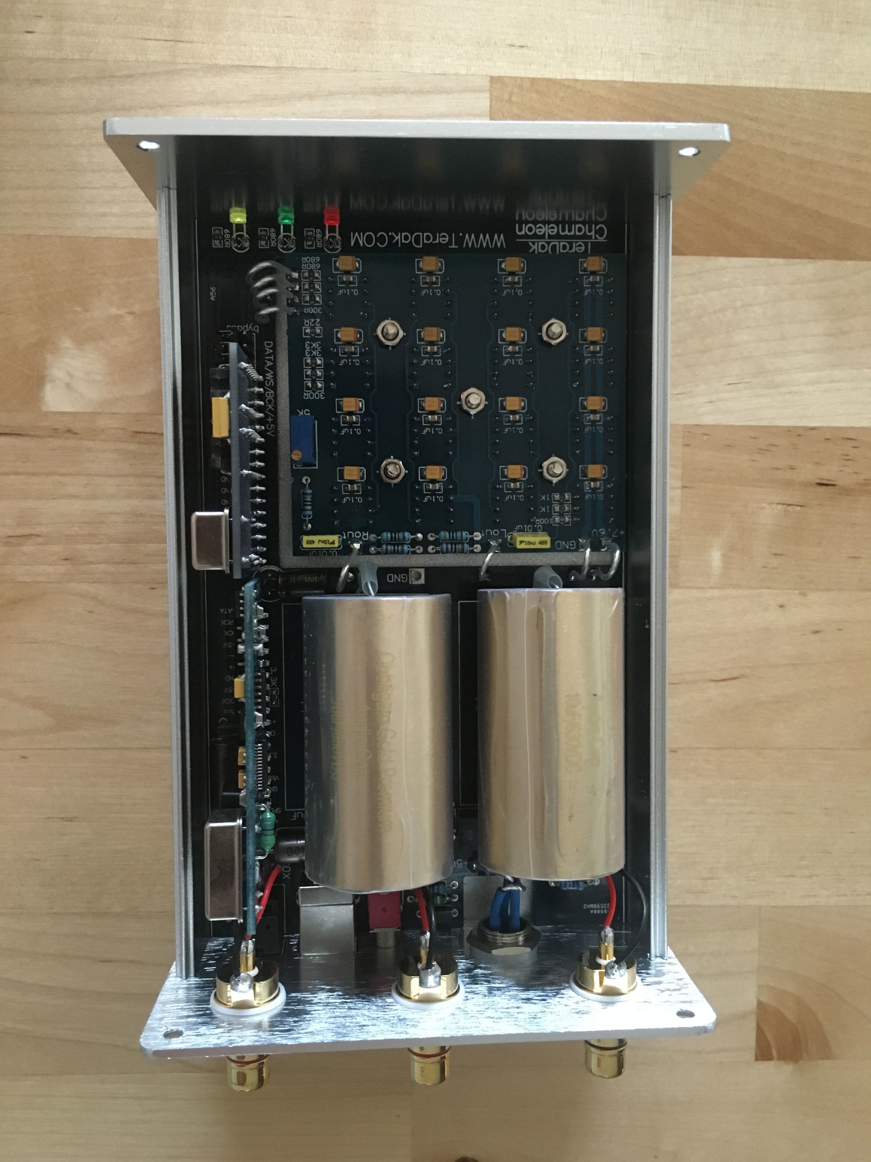
yeah, I saw that, it looks like he put a couple 2k resistors on there. But I don't know what value his original SMD resistors are. It looks like 680 is the correct value? It's confusing. There's another set of resistors above these, that are also labeled
300R
3k3x2
and these resistors actually have the proper values of SMD 332 (3.3k) 680 is definitely not 3k3. But the board could be wrong.
300R
3k3x2
and these resistors actually have the proper values of SMD 332 (3.3k) 680 is definitely not 3k3. But the board could be wrong.


