Chameleon DAC listening and modifications
Feb 1, 2010 at 1:21 AM Post #286 of 1,158
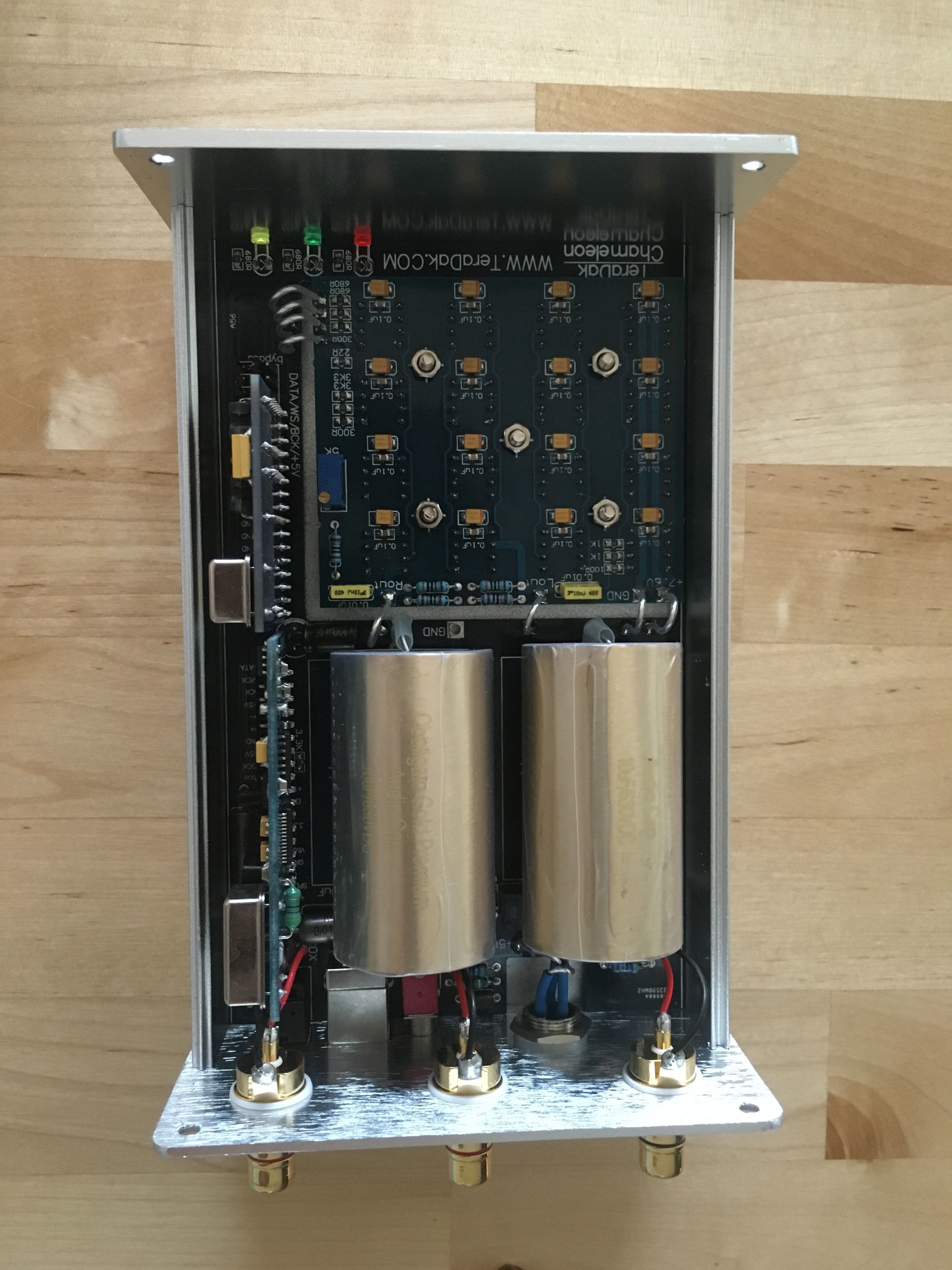
Took a few minutes and tapped the output caps using silver to the DAC for output and you gotta laugh. More swing and flow. I did most of these mods one at a time. I wish I did them all at once - what a rush that would have been.

Now when looking at the board there is slots for twelve DAC caps not sixteen. Is that a hint? I already ordered my TX resistors but may reorder for use with 12 DACs. What is the value I would use for 12 DACs?

changes.jpg
 
Feb 1, 2010 at 1:56 AM Post #287 of 1,158
One of the things that occurs after this SSOM mod is that you can get the flavor of the caps more. I know what the Teflon sounds like when you first pout it in or change to the Obbligatos. That flavor becomes plain and I can tell the Teflons need more burnin to disappear. But this is can be a peripheral sight easily and you can look and look away from it. Just notice it and move on.

The bigger thing is that timbre remains relatively the same, weight as well; It is the individual voices of instruments that gain distinct space and presence. No edge or tip up in space or air or brightness. They just emerge from the mix and become floating presences in a wider stage. I am tempted to use the word 'clarity' but that may imply and edge. Never any edge, ever.

The stretch from the VALAB to the chameleon at this point is worlds apart. The VALAB is a midrange push all of one piece. This Chameleon opens out like a door to the bar with the band inside. Well, right now it is like the door has dropped closed behind me and I am inside.

And all this is without any chemicals involved.

PS. Bass thumps in this gig even with 1uF caps but who can stop now.
 
Feb 1, 2010 at 2:25 AM Post #288 of 1,158
I haven't sat down seriously to compare the sound of the different inputs, but I noticed that the usb doesn't work for me when i use my longer 10ft belkin cable. Luckily i have another 6.5ft belkin that does work, but I would prefer to use my longer one. Don't know if anyone else out there experienced this issue as well. I never had a problem with the longer cable and the Valab dac, but i know they use different usb receiver chips. I've emailed teradak about it, don't know what can be done about this. I use an Apple macbook, but hifi2001 was helping me out with it and we hooked up his Lenovo laptop with the same issue.

also i noted that the add-on boards often come loose and when i turn it on i don't get sound at all out of any of the inputs. the add-on cards is a good idea, but are relatively big and don't sit firmly enough in the socket.

but it's true, even stock and not yet fully burned in, the unit is phenomenal at revealing detail, presence and decent low end presentation. just providing some critical feedback.
 
Feb 1, 2010 at 2:40 AM Post #289 of 1,158
Quote:

Originally Posted by Bill Allen /img/forum/go_quote.gif
Norm- interesting results however I notice you don't have the 47uf FK Blackgates on the DAC chips. Do this then the FRM will do its job.

Understand everything we do to the DAC chip power supply will directly change the sound at the analog output as the stacked DAC chips are our onboard amplification. Balancing this equation is a tough nut to crack and the sky is the limit on how to do this. Look at what Rhodes did for his Valab and what he is proposing to do for his Chameleon power supply.


Guys, thanks for the feedbacks... I guess, it is time to reach in the wallet and buy some 47uF caps... if I want to do FRM mod properly.

Tony, again the laziness in me had me connect 20uF WIMAs to the nearest 7.5 and GND point I could find, interesting comment you made about joining at DAC board, I will definately try it.
 
Feb 1, 2010 at 4:04 AM Post #290 of 1,158
Quote:

Originally Posted by MikeW /img/forum/go_quote.gif
I thought alot of people replaced the Digital Decoupling caps in the old Valab.. the little blue polymer caps all over the digital board. I thought this was the same thing. Looks like i got bigger problems though with this ac all over the place. Wonder if I should try to replace the voltage reg.

Can anyone verify this is the right part?

MJE15030G ON Semiconductor Bipolar Transistors


MikeW, I've been reading about your reported noise issue, couple of suggestions:

1] do you have another DC-30W to try? if not,
2] I wonder if you have a noisy DAC chip? To isolate a noisy DAC chip, the easiest way I found is to remove 4 DAC chips at a time and listen for any noise reduction, if there is no change, proceed with placing back the 4 DACs you just removed and remove another 4 DACs, and so on, until you hear no noise. Next, proceed replacing one DAC chip back at a time. The only caution is to not leave the DAC playing for too long without the heat sink...
 
Feb 1, 2010 at 4:36 AM Post #291 of 1,158
Unfortunately I don't have another DC30 to try. Taking the dac chips out seems like a pain in the ass. I do have a bunch of spare 1543's I could swap out in batches. I think i'll try replacing the voltage reg first. I emailed Michael about caps on the digital section and this is what he had to say

Quote:

In the digital board, we normally use tantalum caps which are suggested by most of the datasheet. The OS-Con caps are used in the power supply. They all should work in the digital board. However, the difference may be not much.

Michael,


edit: can it be just one little dac chip making so much noise?
 
Feb 1, 2010 at 4:58 AM Post #292 of 1,158
Quote:

Originally Posted by MikeW /img/forum/go_quote.gif
edit: can it be just one little dac chip making so much noise?


I didn't believe it until I heard it myself. I recall asking Michael in the past which section on the DAC board he had the most problem with during manufacture and he said the yield rate on those TDA 1543s is something he is not proud off...
 
Feb 1, 2010 at 10:01 AM Post #293 of 1,158
Quote:

Originally Posted by PatOMalley /img/forum/go_quote.gif
What is the value I would use for 12 DACs?

changes.jpg


I figure the formula Teradak use must be something like;

r = 2800 x 1/n

r = resistance, n = number of chips.

So n=8 would be 350r

n=16 would be 175r

and n= 12 would be 233 r
 
Feb 1, 2010 at 6:18 PM Post #294 of 1,158
Added a 2.2 wima to the 2x 10uf wimas, changed the earth spidf wire to silver, and shortend the Jupiter cap leads and replaced them with silver( thanks pat ). Then at last connected them directly to the dac board, removing the existing links.

Unfortunatly I don't have pats, rolled on virgins thighs, silver, just common or garden 99.999% purity stuff. I use silver speaker cables and interconnects, and of cause, hook up wire, so I should be used to it, but just these little pieces today really did improve the sq a lot, more realistic/velvety. Great stuff!

Next up will try wiring the power input direct to the chip board thus avoiding the copper tracks.
 
Feb 2, 2010 at 1:12 AM Post #295 of 1,158
Looks like the source of my noise, is the Reclocker board. I pulled the board, set the jumpers and the noise dropped dramatically. To bad it does not sound nearly as good without it. Wonder if there is something wrong with mine.
 
Feb 2, 2010 at 3:01 AM Post #296 of 1,158
Quote:

Originally Posted by MikeW /img/forum/go_quote.gif
Looks like the source of my noise, is the Reclocker board. I pulled the board, set the jumpers and the noise dropped dramatically. To bad it does not sound nearly as good without it. Wonder if there is something wrong with mine.


Please check the following:
There are three SMD resistors next to the three LEDs... I believe two are labeled 3.3K and one is 330 on the PCB, If you go to Pat's first post at the beginning of this thread Pat used two metal film resistors there. The value of the 3.3K labeled SMD resistors should read about 680R... I believe the maximum value for these two resistors in-circuit should be no more than 1.5kR. Double check with Michael if yours read higher.
 
Feb 2, 2010 at 7:58 AM Post #298 of 1,158
Mike I'm glad your managing to sort out this hiss problem, must be annoying. I noticed hiss in the reclocker, it must be louder in your setup

http://www.head-fi.org/forums/f7/cha...ml#post6348733

In fact my reclocker stopped working completly about a week ago. Still waiting for Michael to get back to me about this, , I guess he is very busy at the moment.
 
Feb 2, 2010 at 8:17 AM Post #299 of 1,158
I went thru alot of hassle, unfortunately I did try changing out the dac chips, 2 at a time, and got them mixed up, and one of the replacement ones I put in had more noise then the originals. That was a damn mess to get sorted. I did order another voltage regulator but im not so sure it's necessary now.

Michael told me to measure the AC out of a batteries. I measured a single CR123 lithium battery, and I was getting trace amounts of AC off it. between 0.00 and 0.01. When I measured 2 CR123's in series (6v) there was no sign of AC. This suggest that perhaps my meter picks up AC at extremely low voltages, when there is in fact no ac. This also would explain why I don't see ac on the 7.5v rail and I do see it on the 5v. I was just trying to find the source of this noise. I do feel a little stupid for not pulling that reclock board sooner, should have started with the simple things, live and learn. What value of resistors do I need to install "on top" of the SMD 680's to get the correct value?
 

Users who are viewing this thread

Back
Top