Bijou All Tube Futterman Headphone Amplifier
Mar 20, 2008 at 8:35 AM Post #226 of 4,278
Still didn't install the volume and NFB pots. Changed plans and wired the right channel amp heaters up. Powered up with meter across ps output. Heater right channel led lights up green. More importantly right channel tubes heaters lit up. PS voltage was 252vdc, so I adj. for 250vdc. Still on schedule, as slow as it may be.
 
Mar 20, 2008 at 12:54 PM Post #227 of 4,278
Quote:

Originally Posted by ericj /img/forum/go_quote.gif
That's stamped aluminum actually. And they didn't bother to finish the edges, either, so I'm going to have to file them down before painting.

I haven't finished building it so I'm not sure how it sounds. I'm using 6n1p-ev and 6n6p, fwiw. And i have ever so many 'phones to choose from, so I'm not sure where I'll start with it.

All i have left is star ground. I could have finished it tonight but i can't find my box of lugs. If i still can't find it tomorrow I'll just buy more. I'm also missing some of the hardware i need to hold the enclosure together - used to be held together with rivets. Using speednuts and screws, except i have the wrong screws, and didn't buy enough speednuts.


ericj, don't forget that you need to change the cathode resistor (R2) for the 6N1P. Values are listed in the Tweaks section on the website.
 
Mar 20, 2008 at 2:41 PM Post #228 of 4,278
Quote:

Originally Posted by runeight /img/forum/go_quote.gif
ericj, don't forget that you need to change the cathode resistor (R2) for the 6N1P. Values are listed in the Tweaks section on the website.


Yeah, i did observe that necessity.
 
Mar 20, 2008 at 9:18 PM Post #229 of 4,278
My Power Supply lives!!! (Yes, I know the Gold banana plugs on the meter should not be touched or licked at this particular time).

pstesting.jpg


Pardon the casework, I wanted to do a full mockup in pine so I can learn everything I did wrong so I won't do it when I invest in some hardwood
smily_headphones1.gif


Amphead, I ended up investing in a hand <gasp> coping saw, it worked wonders for the square cutouts, along with the file for finishing it up. Next on my list is some calipers, instead of trying to eyeball and trace the part.

Parts Express parts didn't arrive today, so I am still waiting to get the cable arranging supplies before doing too much more. I guess I could mount the other two boards and stare at it
smily_headphones1.gif
 
Mar 20, 2008 at 9:59 PM Post #230 of 4,278
You could also use a veneer over pine, but the thickness of the chassis can be a pain for mounting pots. But in your case without an aluminum frame, Mazukis suggestion of countersunk knobs can get the pots mounted the easy/usual way. Happy to hear your PS was working. :wink: 
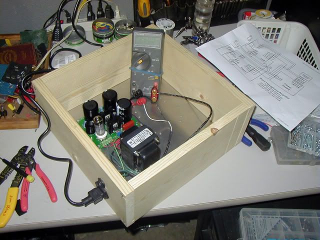
I will wire up the left channel heaters today and get the volume pot mounted.
 
Mar 21, 2008 at 5:01 AM Post #232 of 4,278
Wired up left channel heaters, set the meter up across the PS load resistor. Powered-on and .............#&#&@&$#. No High Voltage, heaters....nothin. Immediately powered down, and checked to see if the fuse was blown. No, fuse was good, so I did a continuity check from transformer hot leads to the PS board connections. Checked out good. Imagined the mosfets had failed, which they had not. Symptoms did not match the fix, because I released the wires on the terminal block and then re-inserted and tightened down on each connection. Powered-on again and........HV good at 249vdc, all tubes heaters on and 2 green leds lit up for the heaters. Very beautiful sight! :wink:
 
Mar 21, 2008 at 8:59 PM Post #233 of 4,278
The saga continues.......powered-on later and no HV. Found 2 possible causes. The load resistor leads did not seem tight enough in the connector. Soldered wires onto the resistor and reinstalled it. Also remembering what Runeight said over on Headwize about soldering the crimp connectors on the star ground was gnawing at me, so I soldered the connectors and re-installed those. HV returns, so I will move onto the volume and NFB pot installations.
 
Mar 22, 2008 at 10:20 PM Post #234 of 4,278
Cutting the oak block for mounting the volume pot and soldering the crimp connectors on the terminal block for 260-0-260vac.
 
Mar 24, 2008 at 9:19 AM Post #236 of 4,278
Finished installing the volume pot/knob assembly onto the oak block on the chassis. Cut a piece of lexan to mount the perfboard on, to allow for a bolt adjustment of the angle of the coupling shaft. A coupling was fashioned out of a 1 and 1/4 inch, 3/8 inch diameter vinyl tubing, onto 1/4 inch brass tubing. This allows for easy disassembly if neccessary, and an unintended benefit is a non-conductive isolation of the knob from the pot. This is a strong and smooth volume manipulation for the amp. Very tedious, but well worth the hassle, that I went through. Only neccessary when the volume pot needs an extension shaft, and can not be mounted directly to the front panel. The NFB pot mounting, and connections to the RCA Jacks are all thats left for the amp board tests and if I'm lucky..........listening.
 
Mar 24, 2008 at 5:28 PM Post #238 of 4,278
I had a busy weekend of non-DIY activity. Also, my parts still did not arrive from PE yet. So I spent some more time laying out things and discovered two things:
Three 20 G wires do NOT fit very well at all into the terminal strips on the board, so I am going to have to use a terminal strip to distribute the heater wiring after all. (Most everybody seems to have already figured this out)
smily_headphones1.gif

It's a PIA mounting jacks and pots on 3/4" stock (I knew it but didn't think it would be quite this bad). To route or drill out the area on the other side I am getting the remaining wood so thin that is doesn't seem substantial enough anymore) I am now going to have an aluminum or plexiglass panel on the front and back. Maybe small ones on the sides too if the plexiglass works out. A see through tube amp)
smily_headphones1.gif


Mazuki: Some masochistic streak in me made me just order the boards from Jeff, and then spend several hours coming up with my own BOM. This kinda started because I wanted to use red turds (PRP) instead of brown turds (Dale) for resistors this time
smily_headphones1.gif
Plus I also already have a collection of pots, jacks, and had already ordered some tubes. I hope the Panasonic caps work out ok, I bought some Nichicon and Panasonics in the 250v rating for the coupling caps on the amp boards to do some comparisons. Might even try the photoflash cap option someday !!

Amphead, good deal on you progress, of course we are interested in your first listening impressions!
 
Mar 24, 2008 at 10:57 PM Post #239 of 4,278
What I have been racking my brains over is how to air-wire the alps pot. This is a PCB pot and I can't figure out how people are air-wiring this thing.

On the other forum I asked and was told "its all very basic just etch a PCB here's the cad file." IMO this should have been included in the kit, unless I am completely missing something. Is there some sort of a femal pin that mates with each pin of the ALPS ?
 

Users who are viewing this thread

Back
Top