Alien DAC v1.1 Construction Thread
Dec 26, 2006 at 5:52 AM Post #526 of 1,562
9V should be fine, might be a bit unwise if there are electrolytics or tantalums that will see the 9V and are rated for 10V and the battery is brand new and somewhat over 9V or one of the 9.6V batteries etc.

Just going by what I've heard that is good to have a bit of room to breathe with those sort of components and they don't like you pushing too close to their max voltage.

edit: Don't jumper, that connects the 5V from the USB to the regs.
 
Dec 29, 2006 at 8:46 AM Post #527 of 1,562
Quote:

Originally Posted by GarlicKnots /img/forum/go_quote.gif
Troubles.

I seem to have a bridge between pin 27 and 28 but it isn't a bridge between the actual pins. It looks like the two pads bridged. I can't seem to get the bridges out between the pads. Tried running the tip over the two pins, tried braid, etc.


Pins 27 and 28 both connect to the ground plane. Mine bridged too, you don't need to worry about it - looking at a fresh board, the solder mask between these pins is nearly nonexistent. If you're getting that power surge message it probably points to a short between power and ground somewhere, but it's not pins 27/28.

That said, I just finished populating my first board. It was a smashing success! After a couple hours of soldering (0805 is nasty...) it's working perfectly with no hiccups. Sounds great too, the noise floor is vanishingly low. All along I thought the noisiness of my rig was due to the cheap Kenwood receiver I'm using as a headamp right now. Not so! It was the cheap SB Live card creating it all -120dB noise floor my ass!

Now, on to a decent amplifier...

Curse you Head-Fi!
 
Dec 30, 2006 at 12:23 AM Post #528 of 1,562
Interesting about 27/28, the first time I read the schematic I thought they were going to different places. I need to take a look again at it.

Anyway, with a 9v battery depleted to ~6.5 I was only able to get these crummy readings:

.43v @ 5v
0 @ 3.3v

I could have easily burnt out the 2702 chip since I thought it's heat tolerance was 10s not the rated 5s.

Going to try another one this weekend and see what happens. Wish me well.
 
Dec 30, 2006 at 12:55 AM Post #529 of 1,562
Quote:

Originally Posted by GarlicKnots /img/forum/go_quote.gif
Interesting about 27/28, the first time I read the schematic I thought they were going to different places. I need to take a look again at it.

Anyway, with a 9v battery depleted to ~6.5 I was only able to get these crummy readings:

.43v @ 5v
0 @ 3.3v

I could have easily burnt out the 2702 chip since I thought it's heat tolerance was 10s not the rated 5s.

Going to try another one this weekend and see what happens. Wish me well.


Do the regs get hot at all? What is the input voltage on the 5V rail with the battery attached? Does the battery get hot? What's the load current on the battery?

If you've got decent input voltage to the regs, but no output, you're probably shorting after the regulators. I suspect though that even a current-limited (at 1A for REG101) short would drag that poor depleted 9V way down. If they're getting hot, that'd confirm this - a short before the regs would give them very little input voltage.

At this point I wouldn't recommend replacing the 2702 just yet. Get the power supplies working first, and if you've still got trouble, replace the 2702. And also try with a more robust power supply - but not without a current limit. A battery depleted that low can probably not source enough current to do any useful work - that may be your only problem. If you've got a bench supply, use that, otherwise 4xAA or breakout the power from a USB cable. Be careful if you use batteries, a dead short across them could be harmful to your health if left for any length of time.

After meeting with failure on the HPDAC and building the Alien, I now wonder why most of the assembly guides for HeadFier's projects recommend soldering down the huge, expensive, sensitive chips rather than building the circuit out modularly where individual parts can be tested. I ignored the assembly guide for my Alien, building the power supply sections first and adding the DAC last as it was then easy to test that nothing was going to get fried. Soldering it all in one go and praying is a bad idea IMO, even if it avoids some awkward soldering (and on this board I didn't have any trouble at all, just don't solder the 'lytics or USB connector until the end - the power supplies don't require any of this for testing). Everyone's likely to make mistakes and they're a nightmare to troubleshoot when the entire circuit is populated - especially if there's more than one error. I would like to petition the circuit designers around here to write their assembly guides in a more modular fashion, with more thought put into testing *during* assembly where troubleshooting is much easier and the consequences less dire.
 
Dec 30, 2006 at 7:08 AM Post #530 of 1,562
Well for me the 2702 was the only thing hard to solder and with nothing else on the board it was that much easier to solder and check for bridges, still a good idea to do it in a modular fashion I suppose.

I did the build in the all at once and hope for the best approach and am dissapointed about it beind dead, however not the power supply that has issues but somethign to do with the 2702. So to me atleast, power supply parts are easier to solder, easier to check. 2702 is a PITA, harder to spot bridges and so far according to myself and others has caused the most problems. So I'd personally still do that first.
 
Dec 30, 2006 at 9:51 AM Post #531 of 1,562
Quote:

Originally Posted by splaz /img/forum/go_quote.gif
Well for me the 2702 was the only thing hard to solder and with nothing else on the board it was that much easier to solder and check for bridges, still a good idea to do it in a modular fashion I suppose.

I did the build in the all at once and hope for the best approach and am dissapointed about it beind dead, however not the power supply that has issues but somethign to do with the 2702. So to me atleast, power supply parts are easier to solder, easier to check. 2702 is a PITA, harder to spot bridges and so far according to myself and others has caused the most problems. So I'd personally still do that first.


Well, something had to have killed the 2702 (if it's in fact dead, which I doubt, though it may be poorly soldered), and if it were a miswired power supply, I'd rather figure that out before desoldering and resoldering a SSOP-28 just to find it fried again. Maybe remove the 2702 that's there to eliminate it as a source of the short, but I wouldn't go as far as replacing it outright, at least without powering the circuit and testing what you can with it removed.

Any chance of some high-res pics?

Good luck
smily_headphones1.gif
.
 
Dec 30, 2006 at 10:00 AM Post #532 of 1,562
Well I covered it earlier in this thread.

Power supplies are fine, 4.71V and 3.3V on their outputs, every single pin has the right readings on their pins except OUTR and OUTL which I get nothing or tiny readings when I should measure around 2.5V or so DC offset, no shorts to ground on either channel. Of course data pins could be doing something, but yeah, I'm assuming the DAC stage in the chip is dead or it's not getting the right data/data is stuffed somehow.

I'm pretty sure I've killed the chip by now anyway as I shorted VBUS to GND when trying to make sure it was right a second time, I slipped, it sparked, mate said "What, don't go blowing the fuse in my laptop".
icon10.gif


That was several hours after it wasn't working anyway and just made me even more bummed out. I'm going to give it a whirl in Linux as per Calroths suggestion, if that doesn't work I'll go to plan b.

edit: I do have some pics, not the best photography and they look more messy than it is IRL.

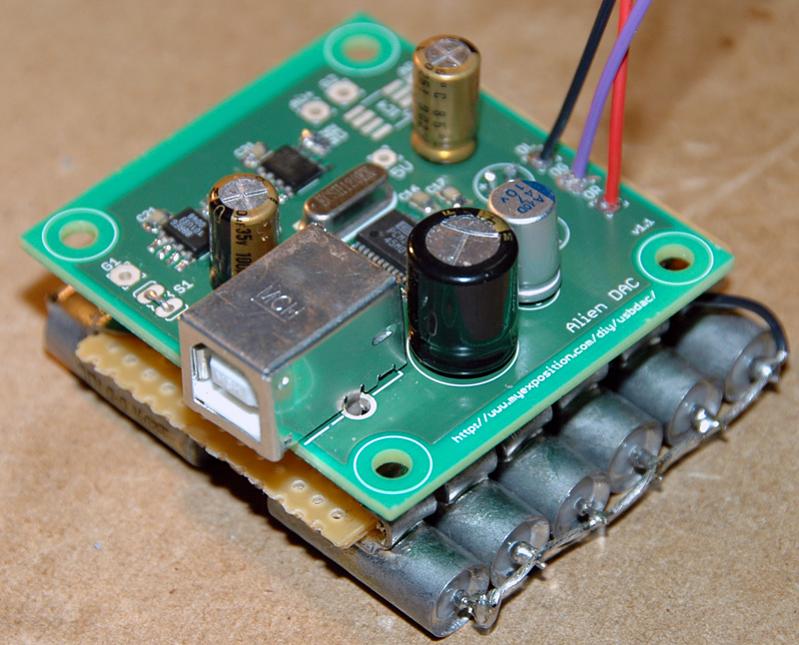
Getting them up now. This is the only good one, second one is more just a shot of what it looks like, cap choice and so on. Bottom is too blurry so I'll retake that and try and get the other side later as the digital camera is out and about at the moment.

Pin 2-3, look rather messy, that's because I lifted a pad due to the misfortune of pushing on the pin in an awkard way with the iron and it bent it sideways a little, massacred the board a little. Checked with a meter for continuity from the cap and it's okay. Get 3.3V and 0V for 2 and 3 so I'm assuming it's not shorted, looks like it is there though. The bit of fluff or whatever it is on the bottom left reg was just some weird loose stuff that would have fallen on it. Doubt it was there when testing and highly doubt it would cause problems anyway as it wasn't bridging anything and power supply outputs were all a-okay.

Oh and lastly, it is detected as a Burr Brown PCM2702(Japan) or whatever it says and USB speakers under device manager. So no problems there, yet no output!


AlienDAC-Top-01

AlienDAC -Top-02
 
Dec 30, 2006 at 10:31 AM Post #533 of 1,562
Well I've removed that little solder ball anyway between those traces and I'll give it a whirl later, I don't have much optimism of it suddenly working though, we'll see after work.
 
Dec 31, 2006 at 5:58 PM Post #534 of 1,562
Hey guys. I've been having the damndest time soldering the DAC chip down. I've tried on all 3 of the PCBs I have and not a single one came out. I think I've got the technique down but need to remove the three chips so I can try again. For some reason I don't seem to be able to remove the solder with braid very well, do you have any suggestions for getting these chips off?
 
Jan 1, 2007 at 4:54 AM Post #536 of 1,562
Quote:

Originally Posted by cgrums /img/forum/go_quote.gif
do you have any suggestions for getting these chips off?


put some braid in flux and then try to unsolder the chip.
 
Jan 1, 2007 at 10:30 AM Post #537 of 1,562
Quote:

Originally Posted by cgrums /img/forum/go_quote.gif
Hey guys. I've been having the damndest time soldering the DAC chip down. I've tried on all 3 of the PCBs I have and not a single one came out. I think I've got the technique down but need to remove the three chips so I can try again. For some reason I don't seem to be able to remove the solder with braid very well, do you have any suggestions for getting these chips off?


Try this method: http://www.infidigm.net/articles/solder/#desoldering

It worked for me
 
Jan 3, 2007 at 4:06 AM Post #539 of 1,562
IT WORKS!!! It only took me four attempts to solder the 2702e but it's currently making beautiful sounds through my maxed out PIMETA. This has definitely been the most challenging/rewarding project I've completed yet. I'm so stoked
eggosmile.gif
 
Jan 3, 2007 at 4:30 PM Post #540 of 1,562
Will this work? I have a PPA headphone amp, and want to install Alien DAC inside it. I already bought the ic4 buffer for aliendac but I have my doubts..my amp uses a 20V power supply, isn't this too much for the alien dac? aren't the regulators getting too hot?
 

Users who are viewing this thread

Back
Top